
Operation Guide
Page 4
Table Of Contents System Communication and Operation ...3-1 Panel Communication with Central Station ...3-1 Report Code Formats...3-1 Ademco Contact ID® ...3-3 Uploading/Downloading via the Internet ...3-4 System Security Codes ...3-5 Panic Keys...3-7 Setting the Real-Time Clock ...3-7 Various System ...Mode)...4-1 Go/No Go Test Mode ...4-2 Dialer Communication Test and Periodic Test Reports 4-2 Automatic Standby Battery Tests...4-2 Specifications & Accessories...5-1 Security Control...5-1 Compatible Devices ...5-1 Regulatory Agency Statements ...6-1 Limitations and Warranty ...7-3 iv
Table Of Contents System Communication and Operation ...3-1 Panel Communication with Central Station ...3-1 Report Code Formats...3-1 Ademco Contact ID® ...3-3 Uploading/Downloading via the Internet ...3-4 System Security Codes ...3-5 Panic Keys...3-7 Setting the Real-Time Clock ...3-7 Various System ...Mode)...4-1 Go/No Go Test Mode ...4-2 Dialer Communication Test and Periodic Test Reports 4-2 Automatic Standby Battery Tests...4-2 Specifications & Accessories...5-1 Security Control...5-1 Compatible Devices ...5-1 Regulatory Agency Statements ...6-1 Limitations and Warranty ...7-3 iv
Operation Guide
Page 5
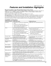
... manual applies to the following Honeywell security systems: ADEMCO VISTA-20P/ADEMCO VISTA-20PSIA/ADEMCO VISTA-20PCN (collectively referred to as VISTA-20P series), ADEMCO VISTA-15P/ADEMCO VISTA-15PSIA/ADEMCO VISTA-15PCN (collectively referred to as SIA compliant, but can be programmed for False Alarm Reduction. SIA Installations: The VISTA-20PSIA and VISTA-15PSIA are noted. zones 9-48) • Up to 2 configurable zone types • Up to 4 configurable...
... manual applies to the following Honeywell security systems: ADEMCO VISTA-20P/ADEMCO VISTA-20PSIA/ADEMCO VISTA-20PCN (collectively referred to as VISTA-20P series), ADEMCO VISTA-15P/ADEMCO VISTA-15PSIA/ADEMCO VISTA-15PCN (collectively referred to as SIA compliant, but can be programmed for False Alarm Reduction. SIA Installations: The VISTA-20PSIA and VISTA-15PSIA are noted. zones 9-48) • Up to 2 configurable zone types • Up to 4 configurable...
Operation Guide
Page 6
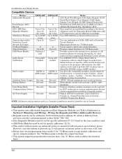
... - Use *57 Menu mode to 48 Partition 1 only Using AAV module 12VDC, 2 AMP output See note. VISTA-15P 8 2 Up to 2 for up to 40 exp. Notes 6150 Fixed-Word Keypad, 6160 Alpha Keypad, 6150V ... Wiring section and set for specific addresses (12-15). • This control will not power-up on the zone numbers used. • 4204 Relay Modules must be Listed for use in...ADEMCO UVS or Eagle Model 1250 in Canada. See note. Can drive the compatible sounders; Use *80 Menu mode to permit voice dialog between an operator at the central station and a person at the premises. zones Up to 26 RF zones...
... - Use *57 Menu mode to 48 Partition 1 only Using AAV module 12VDC, 2 AMP output See note. VISTA-15P 8 2 Up to 2 for up to 40 exp. Notes 6150 Fixed-Word Keypad, 6160 Alpha Keypad, 6150V ... Wiring section and set for specific addresses (12-15). • This control will not power-up on the zone numbers used. • 4204 Relay Modules must be Listed for use in...ADEMCO UVS or Eagle Model 1250 in Canada. See note. Can drive the compatible sounders; Use *80 Menu mode to permit voice dialog between an operator at the central station and a person at the premises. zones Up to 26 RF zones...

Operation Guide
Page 7
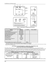
... the cabinet's contents, remove the metal cabinet knockouts required for wiring entry. Make sure that the board rests on the correct row of the control's board into the mounting clips and secure the board to the general public, using 2 screws in Figure 3 on the raised cabinet tabs ... the base of the cabinet, into the slots at the lower edge of the board. SECTION 2 Mounting and Wiring the Control ADEMCO ADEMCO cab_lock_snap-001-V0 Installing the Control Cabinet and PC Board Cabinet and Lock 1. Remove cabinet door, then remove the lock knockout from its case, then insert ...
... the cabinet's contents, remove the metal cabinet knockouts required for wiring entry. Make sure that the board rests on the correct row of the control's board into the mounting clips and secure the board to the general public, using 2 screws in Figure 3 on the raised cabinet tabs ... the base of the cabinet, into the slots at the lower edge of the board. SECTION 2 Mounting and Wiring the Control ADEMCO ADEMCO cab_lock_snap-001-V0 Installing the Control Cabinet and PC Board Cabinet and Lock 1. Remove cabinet door, then remove the lock knockout from its case, then insert ...
Operation Guide
Page 8
... Total Maximum Auxiliary Current Battery Capacity Recommended Battery To Use (Amp/Hrs) (Yuasa Model No.) 600mA maximum total of 45mA 4AH NP4-12 (or ADEMCO 467) auxiliary power plus bell 160mA 7AH NP7-12 output currents 200mA 8AH NP4-12 (two) ‡ 425mA 14AH NP7-12 (two) ‡...30mA 4204 Relay Unit 15/180mA‡ 4229 Zone Expander/Relay Unit 30/100mA‡ 4286 Phone Module 300mA No. IF NO RF RECEIVER IS USED, MOUNT THE PC BOARD USING EITHER THE WHITE OR BLACK CLIPS, WHICHEVER ARE INCLUDED IN THE CONTROL PANEL'S HARDWARE KIT. USE THE APPROPRIATE CLIPS FOR...
... Total Maximum Auxiliary Current Battery Capacity Recommended Battery To Use (Amp/Hrs) (Yuasa Model No.) 600mA maximum total of 45mA 4AH NP4-12 (or ADEMCO 467) auxiliary power plus bell 160mA 7AH NP7-12 output currents 200mA 8AH NP4-12 (two) ‡ 425mA 14AH NP7-12 (two) ‡...30mA 4204 Relay Unit 15/180mA‡ 4229 Zone Expander/Relay Unit 30/100mA‡ 4286 Phone Module 300mA No. IF NO RF RECEIVER IS USED, MOUNT THE PC BOARD USING EITHER THE WHITE OR BLACK CLIPS, WHICHEVER ARE INCLUDED IN THE CONTROL PANEL'S HARDWARE KIT. USE THE APPROPRIATE CLIPS FOR...
Operation Guide
Page 14
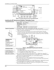
Installation and Setup Guide WHT GRY VIO BLK YEL ORG BRN RELAY CONNECTOR RELAY 2 DIP SWITCH FOR SETTING ADDRESS AND ZONE "A" RESPONSE RELAY 1 NO C NC TAMPER JUMPER POSITION 4229 IN CABINET (NOT TAMPER) 4229 REMOTE (TAMPER PROTECTED) 12 3456 78 4229 EITHER OR BOTH CAN BE USED TERMINALS ON CONTROL PANEL 4-PIN CONSOLE PLUG TB2 4 TB1 9 10 11 12 3 4 3 22 11 GRN DATA OUT (>) TO CONTROL BLK (-) GROUND RED (+) 12VDC YEL DATA IN (
Installation and Setup Guide WHT GRY VIO BLK YEL ORG BRN RELAY CONNECTOR RELAY 2 DIP SWITCH FOR SETTING ADDRESS AND ZONE "A" RESPONSE RELAY 1 NO C NC TAMPER JUMPER POSITION 4229 IN CABINET (NOT TAMPER) 4229 REMOTE (TAMPER PROTECTED) 12 3456 78 4229 EITHER OR BOTH CAN BE USED TERMINALS ON CONTROL PANEL 4-PIN CONSOLE PLUG TB2 4 TB1 9 10 11 12 3 4 3 22 11 GRN DATA OUT (>) TO CONTROL BLK (-) GROUND RED (+) 12VDC YEL DATA IN (

Operation Guide
Page 16
Keyswitch Notes 11 TYPICAL ZONE ON CONTROL BOARD 10 STANDARD KEYPAD CABLE YELLOW 4146 KEYSWITCH (ARMED) RED WHITE (READY) GREEN BLACK RED BROWN 820 ohms 820 ohms TAMPER SWITCH (N. O.) BLUE 00-trigcon-... 05 - C.) BROWN BLUE LOCK SWITCH (N. keyswitch. • Use only one keyswitch per partition. • When using a keyswitch, the zone it zone type 77. • Use *80 Menu mode to a zone's (2-8) terminals. The Ademco 4146 keyswitch is required for fire installations and UL commercial and residential burglar alarm installations. Remove the 2000 ohm EOL resistor...
Keyswitch Notes 11 TYPICAL ZONE ON CONTROL BOARD 10 STANDARD KEYPAD CABLE YELLOW 4146 KEYSWITCH (ARMED) RED WHITE (READY) GREEN BLACK RED BROWN 820 ohms 820 ohms TAMPER SWITCH (N. O.) BLUE 00-trigcon-... 05 - C.) BROWN BLUE LOCK SWITCH (N. keyswitch. • Use only one keyswitch per partition. • When using a keyswitch, the zone it zone type 77. • Use *80 Menu mode to a zone's (2-8) terminals. The Ademco 4146 keyswitch is required for fire installations and UL commercial and residential burglar alarm installations. Remove the 2000 ohm EOL resistor...

Operation Guide
Page 20
... system provides audio alarm verification via the phone line. • Refer to UVCM module terminals 6 & 7, and program the zone as : ZT = 60, P = 0, Action = 1, Device = 18 • Suggested AAV Module: ADEMCO UVS (shown) or Eagle 1250 UL UL installations using the AAV feature must use one of the...81 (*56 Menu mode). Connection of AAV Unit When Not Using a 4286 Phone Module AUXILIARY AUDIO LEVEL ADJUSTMENT TRIM POT CONTROL 45 OUTPUT 18 TRIGGER 5 CONNECTOR ZONE TERMINALS EOL 21 22 23 24 25 EARTH GROUND GND +12VDC UVCM RING MODULE TIP NOTE: REFER TO UVCM MODULE ...
... system provides audio alarm verification via the phone line. • Refer to UVCM module terminals 6 & 7, and program the zone as : ZT = 60, P = 0, Action = 1, Device = 18 • Suggested AAV Module: ADEMCO UVS (shown) or Eagle 1250 UL UL installations using the AAV feature must use one of the...81 (*56 Menu mode). Connection of AAV Unit When Not Using a 4286 Phone Module AUXILIARY AUDIO LEVEL ADJUSTMENT TRIM POT CONTROL 45 OUTPUT 18 TRIGGER 5 CONNECTOR ZONE TERMINALS EOL 21 22 23 24 25 EARTH GROUND GND +12VDC UVCM RING MODULE TIP NOTE: REFER TO UVCM MODULE ...
Operation Guide
Page 23
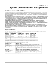
...code, and 3-digit zone number, user number, or system status number (see the following page). 3-1 If the handshake frequency is not given or is not given by the panel, the panel will not send ... is programmed to receive its message. FORMAT TYPE 3+1 and 4+1 Standard Formats 3+1 and 4+1 Expanded Formats 4+2 Format ADEMCO Contact ID Reporting Format DESCRIPTION Comprises a 3- (or 4-) digit subscriber number and a single-digit report code (e.g.,... of communication between the control panel and the Central Station receiver; If there is not successful after its message. Comprises a 4-...
...code, and 3-digit zone number, user number, or system status number (see the following page). 3-1 If the handshake frequency is not given or is not given by the panel, the panel will not send ... is programmed to receive its message. FORMAT TYPE 3+1 and 4+1 Standard Formats 3+1 and 4+1 Expanded Formats 4+2 Format ADEMCO Contact ID Reporting Format DESCRIPTION Comprises a 3- (or 4-) digit subscriber number and a single-digit report code (e.g.,... of communication between the control panel and the Central Station receiver; If there is not successful after its message. Comprises a 4-...
Operation Guide
Page 25
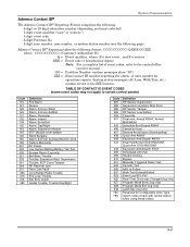
... only) Program Mode Exit (log only) Latch Key (log only) Reserved for open/close reports. System Communication Ademco Contact ID® The Ademco Contact ID® Reporting Format comprises the following: 4-digit or 10-digit subscriber number (depending on format selected)....zone number, user number, or system status number (see the following format: CCCC(CCCCCC) Q EEE GG ZZZ where: CCCC(CCCCCC) =Customer (subscriber) ID Q = Event qualifier, where: E = new event , and R = restore EEE = Event code (3 hexadecimal digits) Note: For a complete list of event codes, refer to certain control panels...
... only) Program Mode Exit (log only) Latch Key (log only) Reserved for open/close reports. System Communication Ademco Contact ID® The Ademco Contact ID® Reporting Format comprises the following: 4-digit or 10-digit subscriber number (depending on format selected)....zone number, user number, or system status number (see the following format: CCCC(CCCCCC) Q EEE GG ZZZ where: CCCC(CCCCCC) =Customer (subscriber) ID Q = Event qualifier, where: E = new event , and R = restore EEE = Event code (3 hexadecimal digits) Note: For a complete list of event codes, refer to certain control panels...

Operation Guide
Page 33
...) self-contained 20-watt sirens. AUXILIARY POWER OUTPUT: 12VDC, 600mA max. The PTC serves as an automatically resetting fuse.) 3. Radionics/SESCOA: Ademco Contact ID 20 pulses/sec, 1800Hz Data Tone, 2300Hz ACK/KISSOFF. Physical: 12-1/2" W x 14-1/2" H x 3" D (318mm x ..., 1400Hz KISSOFF. SECTION 5 Specifications & Accessories Security Control 1. Electrical: VOLTAGE INPUT: 16.5VAC from plug-in 25VA transformer, ADEMCO 1321 (in parallel. Maximum Zone Resistance: Zones 1-8 = 300 ohms excluding EOLR standard zones Compatible Devices Keypads: 6150 Fixed-Word Keypad, 6160 ...
...) self-contained 20-watt sirens. AUXILIARY POWER OUTPUT: 12VDC, 600mA max. The PTC serves as an automatically resetting fuse.) 3. Radionics/SESCOA: Ademco Contact ID 20 pulses/sec, 1800Hz Data Tone, 2300Hz ACK/KISSOFF. Physical: 12-1/2" W x 14-1/2" H x 3" D (318mm x ..., 1400Hz KISSOFF. SECTION 5 Specifications & Accessories Security Control 1. Electrical: VOLTAGE INPUT: 16.5VAC from plug-in 25VA transformer, ADEMCO 1321 (in parallel. Maximum Zone Resistance: Zones 1-8 = 300 ohms excluding EOLR standard zones Compatible Devices Keypads: 6150 Fixed-Word Keypad, 6160 ...

Operation Guide
Page 38
... Test Mode 4-1, 4-2 Trigger outputs 2-12 Trouble Displays 3-7, 3-8 UL 2-2, 2-4, 2-11, 5-1 Verify Operation 2-7 Wire Run Chart 2-4, 2-5 Worksheet 2-2 Zone Doubling 2-6 7-4 Installation and Setup Guide 1321 1-2, 2-3 1321 AC Transformer 2-11 1361X10 2-3, 2-11, 2-12, 5-2 3+1 and 4+1 Standard Formats ....... 3-1... 5802CP 2-9, 3-8 5827 2-9 5827BD 2-9 5881 2-2, 2-8 7720PLUS or 7820 1-2 AC Power Supply 1-2 AC Transformer 2-3, 2-12, 5-2 Ademco Contact ID 3-3 Alarm Output 2-2, 2-4 Arming Away 3-6 Arming Instant 3-6 Arming Modes 3-7 Arming Stay 3-6 Audio Alarm Verification (AAV) ...
... Test Mode 4-1, 4-2 Trigger outputs 2-12 Trouble Displays 3-7, 3-8 UL 2-2, 2-4, 2-11, 5-1 Verify Operation 2-7 Wire Run Chart 2-4, 2-5 Worksheet 2-2 Zone Doubling 2-6 7-4 Installation and Setup Guide 1321 1-2, 2-3 1321 AC Transformer 2-11 1361X10 2-3, 2-11, 2-12, 5-2 3+1 and 4+1 Standard Formats ....... 3-1... 5802CP 2-9, 3-8 5827 2-9 5827BD 2-9 5881 2-2, 2-8 7720PLUS or 7820 1-2 AC Power Supply 1-2 AC Transformer 2-3, 2-12, 5-2 Ademco Contact ID 3-3 Alarm Output 2-2, 2-4 Arming Away 3-6 Arming Instant 3-6 Arming Modes 3-7 Arming Stay 3-6 Audio Alarm Verification (AAV) ...
Operation Guide
Page 39
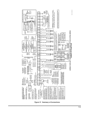
...A CANADIAN INSTALLATION MUST BE LISTED FOR USE IN CANADA 6.2k TYPICAL WIRING FOR ZONE DOUBLING (VISTA-20P ONLY) ADEMCO VISTA-20P / VISTA-20PSIA SERIES / VISTA-15P / VISTA-15PSIA SERIES SUMMARY OF CONNECTIONS LO ZONE 8 HI VISTA-20P ONLY 21 22 23 24 25 TIP RING TIP RING (BROWN) (GRAY...13 6 / 14 7 / 15 8 / 16 POWER SHUTDOWN NOTE: SYSTEM SHUTS DOWN SENSOR DETECTION PROCESSING IF CONTROL'S VOLTAGE DROPS BELOW 9.6V. POWER OUTPUT 10.5-13.8VDC 600mA MAX. (500mA MAX. TO ZONE TERM. ( +) TO ZONE TERM. (_) HEAT DETECTOR } } } Figure 17. CONNECTION OF THE FIRE ALARM SIGNAL TO A FIRE ALARM ...
...A CANADIAN INSTALLATION MUST BE LISTED FOR USE IN CANADA 6.2k TYPICAL WIRING FOR ZONE DOUBLING (VISTA-20P ONLY) ADEMCO VISTA-20P / VISTA-20PSIA SERIES / VISTA-15P / VISTA-15PSIA SERIES SUMMARY OF CONNECTIONS LO ZONE 8 HI VISTA-20P ONLY 21 22 23 24 25 TIP RING TIP RING (BROWN) (GRAY...13 6 / 14 7 / 15 8 / 16 POWER SHUTDOWN NOTE: SYSTEM SHUTS DOWN SENSOR DETECTION PROCESSING IF CONTROL'S VOLTAGE DROPS BELOW 9.6V. POWER OUTPUT 10.5-13.8VDC 600mA MAX. (500mA MAX. TO ZONE TERM. ( +) TO ZONE TERM. (_) HEAT DETECTOR } } } Figure 17. CONNECTION OF THE FIRE ALARM SIGNAL TO A FIRE ALARM ...


