Installation Instructions
Page 1
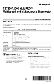
... as provided in instructions and on the product to follow them could damage the product or cause a hazardous condition. 2. TB7100A1000 MultiPRO™ Multispeed and Multipurpose Thermostat APPLICATION INSTALLATION INSTRUCTIONS The TB7100A1000 MultiPRO™ Multispeed and Multipurpose Thermostat provides electronic control of properly. Feature Powering Methods System Types Changeover System Setting Fan Setting Fan Speeds Remote Setback...
... as provided in instructions and on the product to follow them could damage the product or cause a hazardous condition. 2. TB7100A1000 MultiPRO™ Multispeed and Multipurpose Thermostat APPLICATION INSTALLATION INSTRUCTIONS The TB7100A1000 MultiPRO™ Multispeed and Multipurpose Thermostat provides electronic control of properly. Feature Powering Methods System Types Changeover System Setting Fan Setting Fan Speeds Remote Setback...
Installation Instructions
Page 2
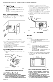
... the mounting screws into the wall opening with good air circulation at average temperature. Radiant heat from Thermostat 1. NOTES: - - - TB7100A1000 MULTIPRO™ MULTISPEED AND MULTIPURPOSE THERMOSTAT CAUTION Electrical Shock or Equipment Damage Hazard. M22258 Fig. 1. Use 18 gauge thermostat wire. Shielded cable is not required. For firmer material such as plaster, drill two 7/32 in...
... the mounting screws into the wall opening with good air circulation at average temperature. Radiant heat from Thermostat 1. NOTES: - - - TB7100A1000 MULTIPRO™ MULTISPEED AND MULTIPURPOSE THERMOSTAT CAUTION Electrical Shock or Equipment Damage Hazard. M22258 Fig. 1. Use 18 gauge thermostat wire. Shielded cable is not required. For firmer material such as plaster, drill two 7/32 in...
Installation Instructions
Page 3
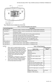
... wire in the Installer Setup, configure changeover valve for heating and cooling, the common must have a cable separate from the thermostat control cable. When using separate transformers for cool (O-factory setting) or heat (B). Wiring Diagrams. System Type Wiring Diagram Figure Standard...setback, or changeover input. Sensor wires must come from secondary side of wire hole. G2 Fan relay. WIRE TB7100A1000 MULTIPRO™ MULTISPEED AND MULTIPURPOSE THERMOSTAT WALLPLATE WALL OPENING SHADED AREA M22266 Fig. 5. Restrict wires to heat pump, PTAC. Medium fan speed for ...
... wire in the Installer Setup, configure changeover valve for heating and cooling, the common must have a cable separate from the thermostat control cable. When using separate transformers for cool (O-factory setting) or heat (B). Wiring Diagrams. System Type Wiring Diagram Figure Standard...setback, or changeover input. Sensor wires must come from secondary side of wire hole. G2 Fan relay. WIRE TB7100A1000 MULTIPRO™ MULTISPEED AND MULTIPURPOSE THERMOSTAT WALLPLATE WALL OPENING SHADED AREA M22266 Fig. 5. Restrict wires to heat pump, PTAC. Medium fan speed for ...
Installation Instructions
Page 4
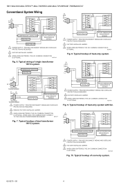
.... 1 L1 (HOT) 3 C W1 G G2 Y G3 24 VAC O/B S1 L2 RC S2 R2 HEAT RELAY FAN RELAY INDOOR TEMPERATURE SENSOR/REMOTE SETBACK 1 POWER SUPPLY. TB7100A1000 MULTIPRO™ MULTISPEED AND MULTIPURPOSE THERMOSTAT Conventional System Wiring L1 1 (HOT) C 3 W1 G G2 Y G3 24 VAC O/B S1 L2 RC S2 R2 COMPRESSOR CONTACTOR FAN RELAY INDOOR TEMPERATURE SENSOR/REMOTE...
.... 1 L1 (HOT) 3 C W1 G G2 Y G3 24 VAC O/B S1 L2 RC S2 R2 HEAT RELAY FAN RELAY INDOOR TEMPERATURE SENSOR/REMOTE SETBACK 1 POWER SUPPLY. TB7100A1000 MULTIPRO™ MULTISPEED AND MULTIPURPOSE THERMOSTAT Conventional System Wiring L1 1 (HOT) C 3 W1 G G2 Y G3 24 VAC O/B S1 L2 RC S2 R2 COMPRESSOR CONTACTOR FAN RELAY INDOOR TEMPERATURE SENSOR/REMOTE...
Installation Instructions
Page 5
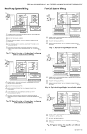
... FACTORY INSTALLED JUMPER. 3 WHEN USING BATTERIES, THE 24V COMMON CONNECTION IS OPTIONAL. M27424 Fig. 14. WIRES MUST HAVE A CABLE SEPARATE FROM THE THERMOSTAT CABLE. L1 (HOT) 3 24 VAC C W1 L2 G G2 1 Y G3 4 O/B S1 RC S2 R2 CHANGEOVER VALVE COMPRESSOR CONTACTOR FAN ... INDOOR TEMPERATURE SENSOR/REMOTE SETBACK/CHANGEOVER PIPE SENSOR HIGH FAN RELAY 1 POWER SUPPLY. M27425 Fig. 15. M27422 Fig. 12. TB7100A1000 MULTIPRO™ MULTISPEED AND MULTIPURPOSE THERMOSTAT Heat Pump System Wiring Fan Coil System Wiring L1 (HOT) 3 24 VAC C W1 L2 G G2 1 Y G3 4...
... FACTORY INSTALLED JUMPER. 3 WHEN USING BATTERIES, THE 24V COMMON CONNECTION IS OPTIONAL. M27424 Fig. 14. WIRES MUST HAVE A CABLE SEPARATE FROM THE THERMOSTAT CABLE. L1 (HOT) 3 24 VAC C W1 L2 G G2 1 Y G3 4 O/B S1 RC S2 R2 CHANGEOVER VALVE COMPRESSOR CONTACTOR FAN ... INDOOR TEMPERATURE SENSOR/REMOTE SETBACK/CHANGEOVER PIPE SENSOR HIGH FAN RELAY 1 POWER SUPPLY. M27425 Fig. 15. M27422 Fig. 12. TB7100A1000 MULTIPRO™ MULTISPEED AND MULTIPURPOSE THERMOSTAT Heat Pump System Wiring Fan Coil System Wiring L1 (HOT) 3 24 VAC C W1 L2 G G2 1 Y G3 4...
Installation Instructions
Page 6
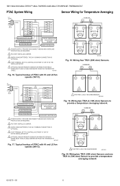
... M27427 Fig. 17. Wiring two TR21 (20K ohm) Sensors and one TR21-A (10K ohm) Sensor to provide a temperature averaging network. TB7100A1000 MULTIPRO™ MULTISPEED AND MULTIPURPOSE THERMOSTAT PTAC System Wiring Sensor Wiring for Temperature Averaging L1 (HOT) 3 24 VAC C W1 L2 G G2 1 Y G3 4 O/B S1...EITHER "O" OR "B" IN THE INSTALLER SETUP. 5 OPTIONAL INDOOR REMOTE SENSOR OR REMOTE SETBACK. WIRES MUST HAVE A CABLE SEPARATE FROM THE THERMOSTAT CABLE. M27482 Fig. 19. Wiring two TR21-A (10K ohm) Sensors to provide a temperature averaging network 62-0273-05 6 M27483 Fig...
... M27427 Fig. 17. Wiring two TR21 (20K ohm) Sensors and one TR21-A (10K ohm) Sensor to provide a temperature averaging network. TB7100A1000 MULTIPRO™ MULTISPEED AND MULTIPURPOSE THERMOSTAT PTAC System Wiring Sensor Wiring for Temperature Averaging L1 (HOT) 3 24 VAC C W1 L2 G G2 1 Y G3 4 O/B S1...EITHER "O" OR "B" IN THE INSTALLER SETUP. 5 OPTIONAL INDOOR REMOTE SENSOR OR REMOTE SETBACK. WIRES MUST HAVE A CABLE SEPARATE FROM THE THERMOSTAT CABLE. M27482 Fig. 19. Wiring two TR21-A (10K ohm) Sensors to provide a temperature averaging network 62-0273-05 6 M27483 Fig...
Installation Instructions
Page 7
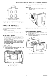
...BACK OF THERMOSTAT Fig. 22. See Fig. 23. Remove the metal jumper wire between RC and R. • Two-Transformer System-Connect the common side of the transformer to Wallplate 1. M22259 7 62-0273-05 Locate and remove the tab labeled Remove. BATTERIES (2) BATTERY HOLDER M23024 Fig. 24. TB7100A1000 MULTIPRO™ MULTISPEED... AND MULTIPURPOSE THERMOSTAT SUBBASE S1 S2 1 C7189 C7189 2.
...BACK OF THERMOSTAT Fig. 22. See Fig. 23. Remove the metal jumper wire between RC and R. • Two-Transformer System-Connect the common side of the transformer to Wallplate 1. M22259 7 62-0273-05 Locate and remove the tab labeled Remove. BATTERIES (2) BATTERY HOLDER M23024 Fig. 24. TB7100A1000 MULTIPRO™ MULTISPEED... AND MULTIPURPOSE THERMOSTAT SUBBASE S1 S2 1 C7189 C7189 2.
Installation Instructions
Page 8
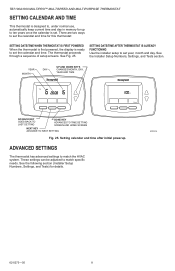
... the installer setup to match the HVAC system. ADVANCED SETTINGS The thermostat has advanced settings to set the calendar and time. TB7100A1000 MULTIPRO™ MULTISPEED AND MULTIPURPOSE THERMOSTAT SETTING CALENDAR AND TIME This thermostat is designed to, under normal use, automatically keep current time and..., month and day. See the following section (Installer Setup Numbers, Settings, and Tests) for this thermostat: SETTING DATE/TIME WHEN THERMOSTAT IS FIRST POWERED When the thermostat is first powered, the display is set the calendar and time for details. There are two ways...
... the installer setup to match the HVAC system. ADVANCED SETTINGS The thermostat has advanced settings to set the calendar and time. TB7100A1000 MULTIPRO™ MULTISPEED AND MULTIPURPOSE THERMOSTAT SETTING CALENDAR AND TIME This thermostat is designed to, under normal use, automatically keep current time and..., month and day. See the following section (Installer Setup Numbers, Settings, and Tests) for this thermostat: SETTING DATE/TIME WHEN THERMOSTAT IS FIRST POWERED When the thermostat is first powered, the display is set the calendar and time for details. There are two ways...
Installation Instructions
Page 9
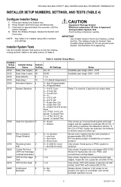
...) 0160 Schedule Options 4 0-Non-Programmable 4-Programmable 0170 System Selection 1 1-1H/1C Conv Relay Y is programmable (ISU 0160). Press and release the System key. 2. TB7100A1000 MULTIPRO™ MULTISPEED AND MULTIPURPOSE THERMOSTAT INSTALLER SETUP NUMBERS, SETTINGS, AND TESTS (TABLE 4) Configure Installer Setup 1. The setting chosen for 2 pipe fan coil output relay. 2-1H w/o fan 3-1H with...
...) 0160 Schedule Options 4 0-Non-Programmable 4-Programmable 0170 System Selection 1 1-1H/1C Conv Relay Y is programmable (ISU 0160). Press and release the System key. 2. TB7100A1000 MULTIPRO™ MULTISPEED AND MULTIPURPOSE THERMOSTAT INSTALLER SETUP NUMBERS, SETTINGS, AND TESTS (TABLE 4) Configure Installer Setup 1. The setting chosen for 2 pipe fan coil output relay. 2-1H w/o fan 3-1H with...
Installation Instructions
Page 10
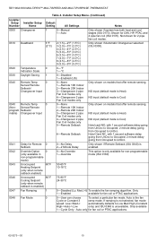
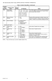
... only 4-Changeover 2 pipe Fan Coil modes only 5-Remote Setback 6-Remote Setback Only shown on models that offer remote sensing. Only available 1-Cycle Only - TB7100A1000 MULTIPRO™ MULTISPEED AND MULTIPURPOSE THERMOSTAT Table 4. Shown for 2 pipe fan coil modes. 0310 Deadband 3°F (2°C) 2 (1.5)-2°F (1.5°C) 3 (2.0)-3°F (2.0°C) 4 (2.5)-4°F (2.5°C) 5 (3.0)-5°F (3.0°C) 6 (3.5)-6°F (3.5°C) 7 (4.0)-7°F (4.0°...
... only 4-Changeover 2 pipe Fan Coil modes only 5-Remote Setback 6-Remote Setback Only shown on models that offer remote sensing. Only available 1-Cycle Only - TB7100A1000 MULTIPRO™ MULTISPEED AND MULTIPURPOSE THERMOSTAT Table 4. Shown for 2 pipe fan coil modes. 0310 Deadband 3°F (2°C) 2 (1.5)-2°F (1.5°C) 3 (2.0)-3°F (2.0°C) 4 (2.5)-4°F (2.5°C) 5 (3.0)-5°F (3.0°C) 6 (3.5)-6°F (3.5°C) 7 (4.0)-7°F (4.0°...
Installation Instructions
Page 11
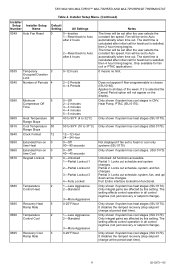
... regimes (not just recovery or setpoint change at period start time is calculated after initial call for heat/cool is satisfied, then 2 hour timing begins. TB7100A1000 MULTIPRO™ MULTISPEED AND MULTIPURPOSE THERMOSTAT Table 4.
... regimes (not just recovery or setpoint change at period start time is calculated after initial call for heat/cool is satisfied, then 2 hour timing begins. TB7100A1000 MULTIPRO™ MULTISPEED AND MULTIPURPOSE THERMOSTAT Table 4.
Installation Instructions
Page 12
... Only shown if system has fan. NOTE: Press the Done key to default energy savings (see Table 5). Only shown if system has fan. TB7100A1000 MULTIPRO™ MULTISPEED AND MULTIPURPOSE THERMOSTAT Installer Setup Number Installer Setup Name 0700 Temperature Display Offset 0710 0720 Restore Factory Defaults Screen Display INSTALLER TESTS Test 1 Installer Test Cool...
... Only shown if system has fan. NOTE: Press the Done key to default energy savings (see Table 5). Only shown if system has fan. TB7100A1000 MULTIPRO™ MULTISPEED AND MULTIPURPOSE THERMOSTAT Installer Setup Number Installer Setup Name 0700 Temperature Display Offset 0710 0720 Restore Factory Defaults Screen Display INSTALLER TESTS Test 1 Installer Test Cool...
Installation Instructions
Page 13
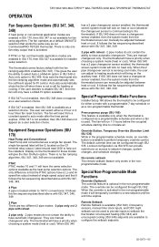
...Unoccupied heating (ISU 343) and unoccupied cooling (ISU 346) setpoints are available to help out the installers. OPERATION TB7100A1000 MULTIPRO™ MULTISPEED AND MULTIPURPOSE THERMOSTAT Fan Sequence Operations (ISU 347, 348, 349) If heat pump or conventional application modes are enabled in ISU 170... control. Remote Setback Remote Setback is available to circulate air. When ISU 340 has a 2 pipe changeover sensor enabled, the thermostat screen system mode will run 1-3 hours before the occupied schedule starting time to perform temporary override control. If ISU 340 does ...
...Unoccupied heating (ISU 343) and unoccupied cooling (ISU 346) setpoints are available to help out the installers. OPERATION TB7100A1000 MULTIPRO™ MULTISPEED AND MULTIPURPOSE THERMOSTAT Fan Sequence Operations (ISU 347, 348, 349) If heat pump or conventional application modes are enabled in ISU 170... control. Remote Setback Remote Setback is available to circulate air. When ISU 340 has a 2 pipe changeover sensor enabled, the thermostat screen system mode will run 1-3 hours before the occupied schedule starting time to perform temporary override control. If ISU 340 does ...
Installation Instructions
Page 14
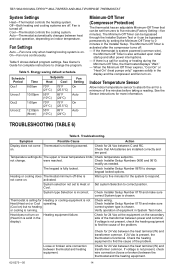
... set from zero to change . Heat does not turn on Heating equipment failure. (Heat On is not come Thermostat is incorrect. Cool-Thermostat controls the cooling system. Table 5 shows default program settings. Check that can be set to five minutes for ...the compressor turns off . If 24 Vac is present, the thermostat is fully locked. TB7100A1000 MULTIPRO™ MULTISPEED AND MULTIPURPOSE THERMOSTAT System Settings Heat-Thermostat controls the heating system. Energy saving default schedule. If the thermostat is system powered (common wire), the Minimum-Off Timer is ...
... set from zero to change . Heat does not turn on Heating equipment failure. (Heat On is not come Thermostat is incorrect. Cool-Thermostat controls the cooling system. Table 5 shows default program settings. Check that can be set to five minutes for ...the compressor turns off . If 24 Vac is present, the thermostat is fully locked. TB7100A1000 MULTIPRO™ MULTISPEED AND MULTIPURPOSE THERMOSTAT System Settings Heat-Thermostat controls the heating system. Energy saving default schedule. If the thermostat is system powered (common wire), the Minimum-Off Timer is ...
Installation Instructions
Page 15
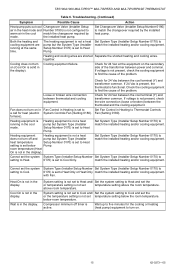
...furnace). Set System Type (Installer Setup Number 0170) to warm air in the heat mode and Number 0190) is set to Thermostat Controls a call for heat (electric System Controls Fan (Setting 0180). match the installed heating and/or cooling equipment. Heat On...Pump. Loose or broken wire connection between the cool terminal (Y) and transformer common. Wait is solid in the display. TB7100A1000 MULTIPRO™ MULTISPEED AND MULTIPURPOSE THERMOSTAT Table 6. Check for 24 Vac at the same time. below Pump. together. room temperature (Heat On is not...
...furnace). Set System Type (Installer Setup Number 0170) to warm air in the heat mode and Number 0190) is set to Thermostat Controls a call for heat (electric System Controls Fan (Setting 0180). match the installed heating and/or cooling equipment. Heat On...Pump. Loose or broken wire connection between the cool terminal (Y) and transformer common. Wait is solid in the display. TB7100A1000 MULTIPRO™ MULTISPEED AND MULTIPURPOSE THERMOSTAT Table 6. Check for 24 Vac at the same time. below Pump. together. room temperature (Heat On is not...
Installation Instructions
Page 16
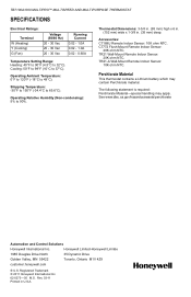
...honeywell.com ® U.S. Rev. 03-11 Printed in . (35 mm) deep. Accessories: C7189U Remote Indoor Sensor: 10K ohm NTC. Thermostat Dimensions: 3-3/4 in. (95 mm) high x 6 in. (152 mm) wide x 1-3/8 in U.S.A. The following statement is required: Perchlorate Material-special handling may contain Perchlorate material. TB7100A1000 MULTIPRO...™ MULTISPEED AND MULTIPURPOSE THERMOSTAT SPECIFICATIONS Electrical Ratings: Terminal W (Heating) Y (Cooling) G (Fan)...
...honeywell.com ® U.S. Rev. 03-11 Printed in . (35 mm) deep. Accessories: C7189U Remote Indoor Sensor: 10K ohm NTC. Thermostat Dimensions: 3-3/4 in. (95 mm) high x 6 in. (152 mm) wide x 1-3/8 in U.S.A. The following statement is required: Perchlorate Material-special handling may contain Perchlorate material. TB7100A1000 MULTIPRO...™ MULTISPEED AND MULTIPURPOSE THERMOSTAT SPECIFICATIONS Electrical Ratings: Terminal W (Heating) Y (Cooling) G (Fan)...


