Installation Instructions
Page 1
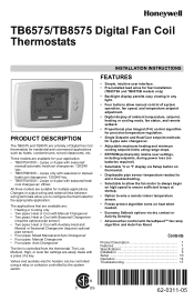
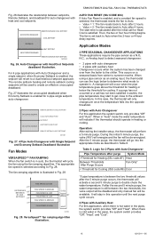
... available for your application: • TB6575A1000 - 2-pipe or 4-pipe with seasonal/ manual/automatic heat/cool changeover; 120/240 Vac. • TB6575B1000 - 2-pipe only with seasonal or manual heat/cool changeover; 120/240 Vac. • TB8575A1000 - 2-pipe or 4-pipe with a press of Digital Fan Coil thermostats for residential and commercial applications such as hotels, condominiums, school classrooms...
... available for your application: • TB6575A1000 - 2-pipe or 4-pipe with seasonal/ manual/automatic heat/cool changeover; 120/240 Vac. • TB6575B1000 - 2-pipe only with seasonal or manual heat/cool changeover; 120/240 Vac. • TB8575A1000 - 2-pipe or 4-pipe with a press of Digital Fan Coil thermostats for residential and commercial applications such as hotels, condominiums, school classrooms...
Installation Instructions
Page 2
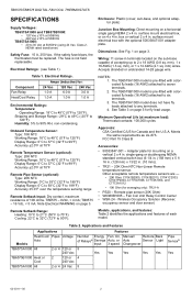
... (0.8 sq. NOTES: 1. The TB8575A1000 model does not have fly leads attached to 90% RH, non-condensing. TB6575/TB8575 DIGITAL FAN COIL THERMOSTATS SPECIFICATIONS Supply Voltages: TB6575A1000 and TB6575B1000: • 120 Vac ±10% at 50/60Hz • 240 Vac ±10% at 50/60Hz TB8575A1000: &#... Applications Models Heat/Cool/ Pipes Voltage Auto TB6575A1000 All 2 or 4 120 or 240 Vac TB6575B1000 Heat or 2 Cool 120 or 240 Vac TB8575A1000 All 2 or 4 24 Vac Features Number Energy Fan: On, Manual/ Remote Back of each model. Note Electrical WARNING on a vertical 2 x 4 in ....
... (0.8 sq. NOTES: 1. The TB8575A1000 model does not have fly leads attached to 90% RH, non-condensing. TB6575/TB8575 DIGITAL FAN COIL THERMOSTATS SPECIFICATIONS Supply Voltages: TB6575A1000 and TB6575B1000: • 120 Vac ±10% at 50/60Hz • 240 Vac ±10% at 50/60Hz TB8575A1000: &#... Applications Models Heat/Cool/ Pipes Voltage Auto TB6575A1000 All 2 or 4 120 or 240 Vac TB6575B1000 Heat or 2 Cool 120 or 240 Vac TB8575A1000 All 2 or 4 24 Vac Features Number Energy Fan: On, Manual/ Remote Back of each model. Note Electrical WARNING on a vertical 2 x 4 in ....
Installation Instructions
Page 5
...sensor (optional) • SB: Remote setback (optional) TB6575/TB8575 DIGITAL FAN COIL THERMOSTATS • Sc: Ground (required if remote sensor, pipe sensor, and/or remote setback are optional. Heat and Cool with Manual Changeover Fly lead wire color Black Orange 9W 9Y 9 W/Y Red ...O Nonee RO RO RO 2 pipes; i Terminal 3 is wired. Heat and Cool with Manual Changeover 4 pipes; Heat and Cool with Manual Changeover 4 pipes; Heat and Cool with Manual Changeover or Auto Changeover 9 W Y 99 9 9 ORO TB6575B1000 - 120/240 Vac Terminal Identifier L W/Y n/ai Gl Gm Gh N Rsa Scb SBc ...
...sensor (optional) • SB: Remote setback (optional) TB6575/TB8575 DIGITAL FAN COIL THERMOSTATS • Sc: Ground (required if remote sensor, pipe sensor, and/or remote setback are optional. Heat and Cool with Manual Changeover Fly lead wire color Black Orange 9W 9Y 9 W/Y Red ...O Nonee RO RO RO 2 pipes; i Terminal 3 is wired. Heat and Cool with Manual Changeover 4 pipes; Heat and Cool with Manual Changeover 4 pipes; Heat and Cool with Manual Changeover or Auto Changeover 9 W Y 99 9 9 ORO TB6575B1000 - 120/240 Vac Terminal Identifier L W/Y n/ai Gl Gm Gh N Rsa Scb SBc ...
Installation Instructions
Page 7
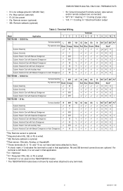
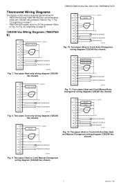
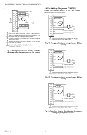
TB6575/TB8575 DIGITAL FAN COIL THERMOSTATS Thermostat Wiring Diagrams The figures in this section illustrate typical wiring for: • TB6575A1000 and TB6575B1000 fan coil thermostats, which is 24 Vac powered. Refer to Fig. 14-Fig. 20, beginning on page 7. • TB8575A1000 model, which are 120/...REMOTE SETBACK Ps M27570 Fig. 11. L L (HOT) W/Y COOL VALVE Y/A GI Gm FAN Gh N N Rs REMOTE SENSOR Sc SB REMOTE SETBACK Ps M27567 Fig. 8. Two pipes (Heat or Cool) with Auxiliary Heat and Manual Changeover wiring diagram (120/240 Vac shown). 7 62-0311-05 Two pipes Cool-only ...
TB6575/TB8575 DIGITAL FAN COIL THERMOSTATS Thermostat Wiring Diagrams The figures in this section illustrate typical wiring for: • TB6575A1000 and TB6575B1000 fan coil thermostats, which is 24 Vac powered. Refer to Fig. 14-Fig. 20, beginning on page 7. • TB8575A1000 model, which are 120/...REMOTE SETBACK Ps M27570 Fig. 11. L L (HOT) W/Y COOL VALVE Y/A GI Gm FAN Gh N N Rs REMOTE SENSOR Sc SB REMOTE SETBACK Ps M27567 Fig. 8. Two pipes (Heat or Cool) with Auxiliary Heat and Manual Changeover wiring diagram (120/240 Vac shown). 7 62-0311-05 Two pipes Cool-only ...
Installation Instructions
Page 8
...be used. Two pipes Cool-only wiring diagram (24 Vac shown). M27575 Fig. 16. TB6575/TB8575 DIGITAL FAN COIL THERMOSTATS . Two pipes Heat-only wiring diagram (24 Vac shown). R W/Y HEAT VALVE Y/A GI Gm FAN L1 Gh 24 VAC (HOT) C L2 1 Rs REMOTE SENSOR Sc SB REMOTE SETBACK Ps 1 ...SETUP IS CODE 9 TO 2 FOR 2 SPEED FAN CONTROL. M31328 Fig. 13. Two pipes (Heat or Cool) Manual Changeover wiring diagram (24 Vac shown). 62-0311-05 8 L W/Y Y/A GI 1 Gm Gh 2 N Rs Sc SB Ps HEAT VALVE COOL VALVE L (HOT) 5 FAN 3 REMOTE SENSOR REMOTE SETBACK N4 1 REMOVE PRE-...
...be used. Two pipes Cool-only wiring diagram (24 Vac shown). M27575 Fig. 16. TB6575/TB8575 DIGITAL FAN COIL THERMOSTATS . Two pipes Heat-only wiring diagram (24 Vac shown). R W/Y HEAT VALVE Y/A GI Gm FAN L1 Gh 24 VAC (HOT) C L2 1 Rs REMOTE SENSOR Sc SB REMOTE SETBACK Ps 1 ...SETUP IS CODE 9 TO 2 FOR 2 SPEED FAN CONTROL. M31328 Fig. 13. Two pipes (Heat or Cool) Manual Changeover wiring diagram (24 Vac shown). 62-0311-05 8 L W/Y Y/A GI 1 Gm Gh 2 N Rs Sc SB Ps HEAT VALVE COOL VALVE L (HOT) 5 FAN 3 REMOTE SENSOR REMOTE SETBACK N4 1 REMOVE PRE-...
Installation Instructions
Page 9
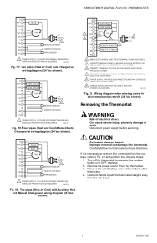
.... TB6575/TB8575 DIGITAL FAN COIL THERMOSTATS R W/Y VALVE Y/A GI Gm FAN Gh 24 VAC L1 (HOT) C L2 1 Rs REMOTE SENSOR Sc SB REMOTE SETBACK Ps PIPE SENSOR 1 POWER SUPPLY. Remove the small safety screw at the bottom of electrical shock. PROVIDE DISCONNECT MEANS AND OVERLOAD PROTECTION AS REQUIRED. Four pipes (Heat and Cool) Manual/Auto Changeover...
.... TB6575/TB8575 DIGITAL FAN COIL THERMOSTATS R W/Y VALVE Y/A GI Gm FAN Gh 24 VAC L1 (HOT) C L2 1 Rs REMOTE SENSOR Sc SB REMOTE SETBACK Ps PIPE SENSOR 1 POWER SUPPLY. Remove the small safety screw at the bottom of electrical shock. PROVIDE DISCONNECT MEANS AND OVERLOAD PROTECTION AS REQUIRED. Four pipes (Heat and Cool) Manual/Auto Changeover...
Installation Instructions
Page 11
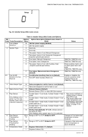
... or 6 for Aux Heat On 7 Four pipes: Manual and Auto Changeover (Default) 0 Fan ON when Auxiliary Heat is on when pipes have cold water (TB6575A, TB8575A only). with Auxiliary Heat (requires optional pipe sensor). 2.5 Fan On/Off Selection for the System Type in ISU code...pipes: Manual Changeover 5 Four pipes: Auto Changeover 6 Two pipes: Heat or Cool; TB6575A, TB8575A only Enables or disables the auto fan operation when Auxiliary Heat is the same as 0) 4 Analog input (Default). Default is 80°F. 90 Changes to 72°F. Setup TB6575/TB8575 DIGITAL FAN COIL THERMOSTATS ...
... or 6 for Aux Heat On 7 Four pipes: Manual and Auto Changeover (Default) 0 Fan ON when Auxiliary Heat is on when pipes have cold water (TB6575A, TB8575A only). with Auxiliary Heat (requires optional pipe sensor). 2.5 Fan On/Off Selection for the System Type in ISU code...pipes: Manual Changeover 5 Four pipes: Auto Changeover 6 Two pipes: Heat or Cool; TB6575A, TB8575A only Enables or disables the auto fan operation when Auxiliary Heat is the same as 0) 4 Analog input (Default). Default is 80°F. 90 Changes to 72°F. Setup TB6575/TB8575 DIGITAL FAN COIL THERMOSTATS ...
Installation Instructions
Page 15
... may start time is in auto, the thermostat will indicate if the thermostat should operate in "Auto" mode the water temperature will cycle the fan using a pipe sensor as a N.O, N.C., or Analog Input to detect seasonal changeover: • 2 pipes with auto changeover • 2 ...5 minute purge, the thermostat will be disabled and only manual fan will revert to Auto after the second 5 minute purge, the water temperature is enabled, the setpoint will be used to Fig. 28. TB6575/TB8575 DIGITAL FAN COIL THERMOSTATS Fig. 26 illustrates the relationship between setpoints, Remote Setback...
... may start time is in auto, the thermostat will indicate if the thermostat should operate in "Auto" mode the water temperature will cycle the fan using a pipe sensor as a N.O, N.C., or Analog Input to detect seasonal changeover: • 2 pipes with auto changeover • 2 ...5 minute purge, the thermostat will be disabled and only manual fan will revert to Auto after the second 5 minute purge, the water temperature is enabled, the setpoint will be used to Fig. 28. TB6575/TB8575 DIGITAL FAN COIL THERMOSTATS Fig. 26 illustrates the relationship between setpoints, Remote Setback...


