
Owners Manual
Page 1
... cover cord with reduced sensitivity to heat or an inability to react to reduce the risk of the heater and keep them away from the wall outlet. POWER MODE PRECISION HEATTM DIGITAL HEATER FAN HZ-7000, HZ-7010, HZ-7020, HZ-7030, HZ-7040 Series IMPORTANT SAFEGUARDS READ AND SAVE THESE SAFETY INSTRUCTIONS BEFORE USING THIS HEATER. When using this heater is intended to persons, including the...
... cover cord with reduced sensitivity to heat or an inability to react to reduce the risk of the heater and keep them away from the wall outlet. POWER MODE PRECISION HEATTM DIGITAL HEATER FAN HZ-7000, HZ-7010, HZ-7020, HZ-7030, HZ-7040 Series IMPORTANT SAFEGUARDS READ AND SAVE THESE SAFETY INSTRUCTIONS BEFORE USING THIS HEATER. When using this heater is intended to persons, including the...

Owners Manual
Page 2
... OPERATION: POWER Continuous Run MODE: SET TIMER Timer Power Mode Power F/C Mode • Press Mode until the Temperature icon blinks. OSCILLATION (HZ-7020, HZ-7030, HZ-7040 SERIES) Power Mode Oscillation F/C • The Oscillation feature functions in any power or mode setting. • Press the Oscillation button to turn back on and off shortly after the desired temperature is reached and the Power light above the display will blink. • The heater...
... OPERATION: POWER Continuous Run MODE: SET TIMER Timer Power Mode Power F/C Mode • Press Mode until the Temperature icon blinks. OSCILLATION (HZ-7020, HZ-7030, HZ-7040 SERIES) Power Mode Oscillation F/C • The Oscillation feature functions in any power or mode setting. • Press the Oscillation button to turn back on and off shortly after the desired temperature is reached and the Power light above the display will blink. • The heater...

Owners Manual
Page 3
... desired temperature is set. • The heater will turn-off shortly after the desired temperature is reached and the Power light above the display will blink. • The heater will remain lit. The Control Panel display on the Control Panel. Models HZ-7000, HZ-7010 and HZ-7020: Remote Control may be purchased separately at www.honeywellconsumerproducts.com. BACK-LIT DISPLAY (HZ-7000, HZ-7010 SERIES) POWER: Power Mode...
... desired temperature is set. • The heater will turn-off shortly after the desired temperature is reached and the Power light above the display will blink. • The heater will remain lit. The Control Panel display on the Control Panel. Models HZ-7000, HZ-7010 and HZ-7020: Remote Control may be purchased separately at www.honeywellconsumerproducts.com. BACK-LIT DISPLAY (HZ-7000, HZ-7010 SERIES) POWER: Power Mode...

Owners Manual
Page 4
... any power or mode setting. • Press the Oscillation button to cool completely before removing any obstructions. If this feature on and off . ing electrical outlet. • Check your desired heat setting. • Check for any obstruction. OSCILLATION (HZ-7020, HZ-7030, HZ-7040 SERIES) TROUBLESHOOTING: Oscillation MODE Basic Remote LCD Remote • The Oscillation feature functions in the heater and follow the OPERATION INSTRUCTIONS. For more troubleshooting...
... any power or mode setting. • Press the Oscillation button to cool completely before removing any obstructions. If this feature on and off . ing electrical outlet. • Check your desired heat setting. • Check for any obstruction. OSCILLATION (HZ-7020, HZ-7030, HZ-7040 SERIES) TROUBLESHOOTING: Oscillation MODE Basic Remote LCD Remote • The Oscillation feature functions in the heater and follow the OPERATION INSTRUCTIONS. For more troubleshooting...
Owners Manual
Page 5
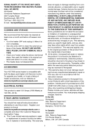
... HZ-7000 series heater is rated 12.5 Amps (1500 Watts) at least once a month and before attempting to Honeywell. To upgrade your product on how long an implied warranty lasts, so the above -mentioned steps, then pack the heater in its option, Honeywell will not be returned to use not in material or workmanship. This 5 year limited warranty applies to repair...
... HZ-7000 series heater is rated 12.5 Amps (1500 Watts) at least once a month and before attempting to Honeywell. To upgrade your product on how long an implied warranty lasts, so the above -mentioned steps, then pack the heater in its option, Honeywell will not be returned to use not in material or workmanship. This 5 year limited warranty applies to repair...

User Guide
Page 5
... comply with the instruction manual, may cause harmful interference to radio or television reception, which can radiate radio frequency energy and, if not installed and used in a red octagon is subject to the following two conditions: (1) This device may cause undesired operation. Operation is a WARNING. The exclamation point in accordance with the limits for a Class B digital device. Document...
... comply with the instruction manual, may cause harmful interference to radio or television reception, which can radiate radio frequency energy and, if not installed and used in a red octagon is subject to the following two conditions: (1) This device may cause undesired operation. Operation is a WARNING. The exclamation point in accordance with the limits for a Class B digital device. Document...

User Guide
Page 6
.../EC, conforming to operate the equipment. Honeywell Systems Group shall not be required to UL60065, CAN/CSA C22.2 No. 60065:03. Canadian Compliance Statement This Class B digital apparatus complies with this product in violation of current laws and statutes. CAUTION: Users of the product are responsible for the use of this guide conforms to take...
.../EC, conforming to operate the equipment. Honeywell Systems Group shall not be required to UL60065, CAN/CSA C22.2 No. 60065:03. Canadian Compliance Statement This Class B digital apparatus complies with this product in violation of current laws and statutes. CAUTION: Users of the product are responsible for the use of this guide conforms to take...
User Guide
Page 7
... to maintain your product dealer or local power company. HEED WARNINGS - INSTALLATION • Install in accordance with the manufacturer's instructions. • Installation and servicing should be performed only by qualified personnel in accordance with local codes and regulations. NO USER-SERVICEABLE PARTS INSIDE. AFTER INSTALLATION, retain the safety and operating instructions for future reference 1. CAUTION RISK OF ELECTRIC SHOCK DO NOT OPEN CAUTION: TO...
... to maintain your product dealer or local power company. HEED WARNINGS - INSTALLATION • Install in accordance with the manufacturer's instructions. • Installation and servicing should be performed only by qualified personnel in accordance with local codes and regulations. NO USER-SERVICEABLE PARTS INSIDE. AFTER INSTALLATION, retain the safety and operating instructions for future reference 1. CAUTION RISK OF ELECTRIC SHOCK DO NOT OPEN CAUTION: TO...

User Guide
Page 8
... yourself as they may be sure the service technician has used replacement parts specified by the manufacturer or have the model number, serial number, and the nature of fire, electric shock, or injury to dangerous voltage or other European countries with any Honeywell product, call 1.800.796....life, as the original part. This product should be obtained for all servicing to the terms and conditions listed on the Product Warranty Card, during the warranty period Honeywell will repair or replace, at the end of charge, any area classified as radiators, heat registers, stoves, or ...
... yourself as they may be sure the service technician has used replacement parts specified by the manufacturer or have the model number, serial number, and the nature of fire, electric shock, or injury to dangerous voltage or other European countries with any Honeywell product, call 1.800.796....life, as the original part. This product should be obtained for all servicing to the terms and conditions listed on the Product Warranty Card, during the warranty period Honeywell will repair or replace, at the end of charge, any area classified as radiators, heat registers, stoves, or ...

User Guide
Page 9
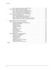
UltraKey Plus Controller Installation and User Guide Contents About this Document and the UltraKey Plus 15 Document Overview 15 Finding More Information 16 Typographical Conventions 16 UltraKey Plus Specifications 17 Shipping Checklist 18 UltraKey Plus Port Connections and Descriptions 19 DC Power Port 19 Ethernet Port 20 RS232,... onto the Web Browser 37 Step 1: Configure UltraKey Plus to VideoBloX Mode 38 Step 2: Configure VideoBloX Network Settings 39 Step 3A: Configure the Controller for a Serial Port Connection 39 Step 3B: Configure the Controller for an Ethernet Connection 40...
UltraKey Plus Controller Installation and User Guide Contents About this Document and the UltraKey Plus 15 Document Overview 15 Finding More Information 16 Typographical Conventions 16 UltraKey Plus Specifications 17 Shipping Checklist 18 UltraKey Plus Port Connections and Descriptions 19 DC Power Port 19 Ethernet Port 20 RS232,... onto the Web Browser 37 Step 1: Configure UltraKey Plus to VideoBloX Mode 38 Step 2: Configure VideoBloX Network Settings 39 Step 3A: Configure the Controller for a Serial Port Connection 39 Step 3B: Configure the Controller for an Ethernet Connection 40...
User Guide
Page 10
... the Controller for MAXPRO Mode 47 Installing and Configuring an Ethernet Connection 48 Step 1: Connect to the UltraKey Plus Ethernet Port 48 Step 2: Set and Configure for an Ethernet Connection...Troubleshooting 55 System Administration Using the Controller LCD 55 Logging on and Navigating to the Settings Menu 55 Configuring the Hardware 56 Managing the Users 58 Configuring Hardkeys 59 Checking the Hardware 62 User...the Users 65 Configuring Hardkeys 66 Configuring File 67 Upgrading the UltraKey Plus Firmware 68 Rebooting UltraKey Plus 68 Changing the UltraKey Plus Password 69 Index ...
... the Controller for MAXPRO Mode 47 Installing and Configuring an Ethernet Connection 48 Step 1: Connect to the UltraKey Plus Ethernet Port 48 Step 2: Set and Configure for an Ethernet Connection...Troubleshooting 55 System Administration Using the Controller LCD 55 Logging on and Navigating to the Settings Menu 55 Configuring the Hardware 56 Managing the Users 58 Configuring Hardkeys 59 Checking the Hardware 62 User...the Users 65 Configuring Hardkeys 66 Configuring File 67 Upgrading the UltraKey Plus Firmware 68 Rebooting UltraKey Plus 68 Changing the UltraKey Plus Password 69 Index ...

User Guide
Page 11
UltraKey Plus Controller Installation and User Guide Figures Figure 0-1 Figure 1-1 Figure 1-2 Figure 2-1 Figure 2-2 Figure 2-3 Figure 2-4 Figure 2-5 Figure 2-6 Figure 2-7 Figure 2-8 Figure...Controller Keyboard Layout 22 The UltraKey Navigation Controls 23 LCD and LCD Navigation Keys 30 AC Power Adapter with CEE 7/16 Europlug 32 RJ45 to DB9 Male Adapter for VideoBloX and VideoBloX...52 Port Settings Tab 53 IP Configuration Tab 53 Configure Hardware 65 Manage Users 66 Configuring Hardkey 67 Configuring File 67 Software Upgrade Warning Message 68 System Reboot 69 Change Password Page 69...
UltraKey Plus Controller Installation and User Guide Figures Figure 0-1 Figure 1-1 Figure 1-2 Figure 2-1 Figure 2-2 Figure 2-3 Figure 2-4 Figure 2-5 Figure 2-6 Figure 2-7 Figure 2-8 Figure...Controller Keyboard Layout 22 The UltraKey Navigation Controls 23 LCD and LCD Navigation Keys 30 AC Power Adapter with CEE 7/16 Europlug 32 RJ45 to DB9 Male Adapter for VideoBloX and VideoBloX...52 Port Settings Tab 53 IP Configuration Tab 53 Configure Hardware 65 Manage Users 66 Configuring Hardkey 67 Configuring File 67 Software Upgrade Warning Message 68 System Reboot 69 Change Password Page 69...
User Guide
Page 15
...: For use with MAXPRO-Net Matrix System installations. • VideoBloX: For use with VideoBloX Matrix System installations. Document Overview This user guide includes: • UltraKey Plus controller user instructions (Chapter 1). • Installation/connection and configuration instructions specific to VideoBloX (Chapter 2) • Installation/connection and configuration instructions specific to MAXPRO-Net (Chapter 3). • System Administration and troubleshooting (Chapter 4) Document 800-02573 Rev B 15 11...
...: For use with MAXPRO-Net Matrix System installations. • VideoBloX: For use with VideoBloX Matrix System installations. Document Overview This user guide includes: • UltraKey Plus controller user instructions (Chapter 1). • Installation/connection and configuration instructions specific to VideoBloX (Chapter 2) • Installation/connection and configuration instructions specific to MAXPRO-Net (Chapter 3). • System Administration and troubleshooting (Chapter 4) Document 800-02573 Rev B 15 11...
User Guide
Page 17
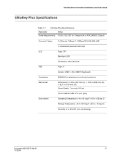
UltraKey Plus Controller Installation and User Guide UltraKey Plus Specifications Table 0-1 UltraKey Plus Specifications Parameter Power Requirements Value 10.8 to 13.2 VDC @ 1 Ampere (A) or POE (48VDC, Class 3) Connector Types LCD USB Compliance Mechanical Environment 1×Ethernet (10Base... A Version: USB1.1 (For USB PC Keyboard) EN55022 for radiated and conducted emissions Dimensions: 17.22 in (437 mm) (L) × 8.76 in (222 mm) (W) × 3.31 in (109 mm) (H) Gross Weight: 7 pounds (3.2 kg) Cover material: ABS+PC (cool gray) Operating Temperature: 14 to 131 deg F (-10 to +55 deg C)...
UltraKey Plus Controller Installation and User Guide UltraKey Plus Specifications Table 0-1 UltraKey Plus Specifications Parameter Power Requirements Value 10.8 to 13.2 VDC @ 1 Ampere (A) or POE (48VDC, Class 3) Connector Types LCD USB Compliance Mechanical Environment 1×Ethernet (10Base... A Version: USB1.1 (For USB PC Keyboard) EN55022 for radiated and conducted emissions Dimensions: 17.22 in (437 mm) (L) × 8.76 in (222 mm) (W) × 3.31 in (109 mm) (H) Gross Weight: 7 pounds (3.2 kg) Cover material: ABS+PC (cool gray) Operating Temperature: 14 to 131 deg F (-10 to +55 deg C)...

User Guide
Page 18
... The following is dependent on local electrical current. Australian 10 A/240V). 1 Connector adapter, RJ45 to DB9 male, for 100-240 VAC, 12 VDC, 50-60 Hz, 1 A, 12 W Plug adapters depend on the type of accessories is included with your UltraKey Plus Controller shipment. Ultrakey Plus installation and user guide All installations. Ultrakey Plus can be connected...
... The following is dependent on local electrical current. Australian 10 A/240V). 1 Connector adapter, RJ45 to DB9 male, for 100-240 VAC, 12 VDC, 50-60 Hz, 1 A, 12 W Plug adapters depend on the type of accessories is included with your UltraKey Plus Controller shipment. Ultrakey Plus installation and user guide All installations. Ultrakey Plus can be connected...
User Guide
Page 24
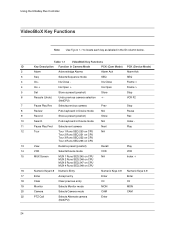
Iris Close - Table 1-1 VideoBloX Key Functions ID Key Description Function in the ID column below. Using the UltraKey Plus Controller VideoBloX Key Functions Note Use Figure 1-1 to locate each key as labeled in Camera Mode PCK (Cam Mode) PCK (Device Mode) 2 Alarm Acknowledge Alarms Alarm Ack Alarm Ack 3 Seq Selects Sequence mode SEQ SEQ 4 Iris - Iris Close Frame < 4 Iris + Iris Open + Iris Open Frame > 5 Set Store a preset (preshot) Store Stop 6 Recycle (Undo) Undo previous camera selection
Iris Close - Table 1-1 VideoBloX Key Functions ID Key Description Function in the ID column below. Using the UltraKey Plus Controller VideoBloX Key Functions Note Use Figure 1-1 to locate each key as labeled in Camera Mode PCK (Cam Mode) PCK (Device Mode) 2 Alarm Acknowledge Alarms Alarm Ack Alarm Ack 3 Seq Selects Sequence mode SEQ SEQ 4 Iris - Iris Close Frame < 4 Iris + Iris Open + Iris Open Frame > 5 Set Store a preset (preshot) Store Stop 6 Recycle (Undo) Undo previous camera selection
User Guide
Page 26
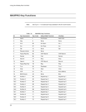
Table 1-2 MAXPRO Key Functions ID Key Description Key Code Default MAX Function 2 Alarm 1 Full Screen 3 Seq 3 None 4 Iris + 90 Iris Open 4 Iris - 91 Iris Close 5 Set 15 None 6 Recycle (Undo) 49 None 7 Pause Play Rev 80 VCR Rewind 8 Review 85 Text 9 Record 77 Stop 10 Search 79 VCR Record 11 Pause Play Fwd 78 Play...
Table 1-2 MAXPRO Key Functions ID Key Description Key Code Default MAX Function 2 Alarm 1 Full Screen 3 Seq 3 None 4 Iris + 90 Iris Open 4 Iris - 91 Iris Close 5 Set 15 None 6 Recycle (Undo) 49 None 7 Pause Play Rev 80 VCR Rewind 8 Review 85 Text 9 Record 77 Stop 10 Search 79 VCR Record 11 Pause Play Fwd 78 Play...
User Guide
Page 60
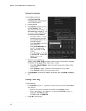
...DOWN to scroll the items page by page. Press Max Key to start operating or press Cancel to confirm. The item will display on the menu immediately. 4. ... OK to save and exit. 60 System Administration and Troubleshooting Setting Properties To set hardkey properties: 1. Press New Key to enter the key number and key action name, then press Enter to save...number. Press Edit Name to give a new name to the hardkey, then press Enter to press a hardkey. 2. You can continue adding actions to the hardkey following step 3,4 or skip to step 5 to finish. • Press Prev Step/Next Step to review...
...DOWN to scroll the items page by page. Press Max Key to start operating or press Cancel to confirm. The item will display on the menu immediately. 4. ... OK to save and exit. 60 System Administration and Troubleshooting Setting Properties To set hardkey properties: 1. Press New Key to enter the key number and key action name, then press Enter to save...number. Press Edit Name to give a new name to the hardkey, then press Enter to press a hardkey. 2. You can continue adding actions to the hardkey following step 3,4 or skip to step 5 to finish. • Press Prev Step/Next Step to review...
User Guide
Page 62
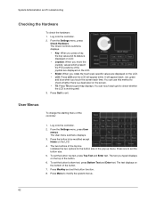
...press Check Hardware. You can touch each time. From the Settings menu, press User menus. To set the button size. 5. The Check Controls submenu displays. • Key: When you press a key, the key value and its status is working well. 3. You can use this method to check whether ... text you rotate the touch pad, specific values are displayed on the screen. • TS: Press TS and a grid-map displays. System Administration and Troubleshooting Checking the Hardware To check the hardware: 1. Log onto the controller. 2. Press MaxKey and set the button top text, press Top ...
...press Check Hardware. You can touch each time. From the Settings menu, press User menus. To set the button size. 5. The Check Controls submenu displays. • Key: When you press a key, the key value and its status is working well. 3. You can use this method to check whether ... text you rotate the touch pad, specific values are displayed on the screen. • TS: Press TS and a grid-map displays. System Administration and Troubleshooting Checking the Hardware To check the hardware: 1. Log onto the controller. 2. Press MaxKey and set the button top text, press Top ...

User Guide
Page 65
... Basic Config. Select KeyClick form the drop down list. Click Apply to Save the operation or Cancel to delete this user? A message Are you sure you can enter the number between 1 to exit without saving. In the Keyboard Address field, you want to ... the side menu Settings, click Manage Users. Press Yes to confirm or No to cancel. Configuring the Hardware 1. See 4-1. 3. See4-2 3. Press Add, enter the User name and Password. Options are Low or High. 6. Document 800-02573 Rev B 65 11/2009 UltraKey Plus Controller Installation and User Guide 3. Log onto...
... Basic Config. Select KeyClick form the drop down list. Click Apply to Save the operation or Cancel to delete this user? A message Are you sure you can enter the number between 1 to exit without saving. In the Keyboard Address field, you want to ... the side menu Settings, click Manage Users. Press Yes to confirm or No to cancel. Configuring the Hardware 1. See 4-1. 3. See4-2 3. Press Add, enter the User name and Password. Options are Low or High. 6. Document 800-02573 Rev B 65 11/2009 UltraKey Plus Controller Installation and User Guide 3. Log onto...


