
Owner's Manual
Page 1
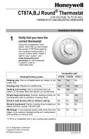
...) with no auxiliary or backup heat. No No * CT87A is right for your system, visit www.honeywell.com/ yourhome or call Honeywell Customer Care at 1-800-468-1502. Installation Instructions Compatible with: Heating/Cooling system CT87A CT87B CT87J Heating only: Gas or oil fueled warm air... Outdoor heating/cooling unit No (compressor) with auxiliary or backup heat. CT87A,B,J Round® Thermostat LOW VOLTAGE (15 TO 30 VAC), THERMOSTAT AND MOUNTING HARDWARE 1 Verify that you have the correct thermostat Using the compatibility chart below, verify that you are unsure which model ...
...) with no auxiliary or backup heat. No No * CT87A is right for your system, visit www.honeywell.com/ yourhome or call Honeywell Customer Care at 1-800-468-1502. Installation Instructions Compatible with: Heating/Cooling system CT87A CT87B CT87J Heating only: Gas or oil fueled warm air... Outdoor heating/cooling unit No (compressor) with auxiliary or backup heat. CT87A,B,J Round® Thermostat LOW VOLTAGE (15 TO 30 VAC), THERMOSTAT AND MOUNTING HARDWARE 1 Verify that you have the correct thermostat Using the compatibility chart below, verify that you are unsure which model ...
Owner's Manual
Page 2
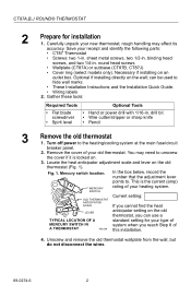
... when you can be used to unscrew the cover if it is the current (amp) MERCURY SWITCH rating of your old thermostat. CT87A,B,J ROUND® THERMOSTAT 2 Prepare for your type of M20206 this installation. 4. Turn off power to . binding head screws, and two 1/4-in . rough handling may need to hide wall marks. • These...
... when you can be used to unscrew the cover if it is the current (amp) MERCURY SWITCH rating of your old thermostat. CT87A,B,J ROUND® THERMOSTAT 2 Prepare for your type of M20206 this installation. 4. Turn off power to . binding head screws, and two 1/4-in . rough handling may need to hide wall marks. • These...
Owner's Manual
Page 3
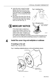
...thermostat is replacing a control that came with the CT87. Disconnect the wires from the old thermostat and wrap them around a pencil to Fig. 4 as you work. Contact your old control in a sealed tube. 4 Install... the cover ring and wallplate or subbase If installing... 4 X 1 INCH SHEET METAL SCREWS (2) 3 THERMOSTAT WIRING OPENING M20188 69-0274-6 Wrapping wires. M19086 MERCURY NOTICE Fig. 3. Installing wallplate/subbase on the wall Refer to keep them...
...thermostat is replacing a control that came with the CT87. Disconnect the wires from the old thermostat and wrap them around a pencil to Fig. 4 as you work. Contact your old control in a sealed tube. 4 Install... the cover ring and wallplate or subbase If installing... 4 X 1 INCH SHEET METAL SCREWS (2) 3 THERMOSTAT WIRING OPENING M20188 69-0274-6 Wrapping wires. M19086 MERCURY NOTICE Fig. 3. Installing wallplate/subbase on the wall Refer to keep them...
Owner's Manual
Page 4
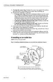
... two 1-in . BINDING HEAD SCREW (2) OUTLET BOX 1 2 COVER RING SUBBASE 1/4 IN. holes at the locations you work. Use a pencil to Fig. 5 as you marked. 5. Installing wallplate/subbase on an outlet box Refer to mark the center of the screw holes on the left and right side of the wallplate/subbase... align with the screw holes on the left and right sides of the cover ring is on the top. 3. CT87A,B,J ROUND® THERMOSTAT 1. If using cover ring: Place the wallplate/subbase over the holes, pull the wires through these holes into the drilled holes.
... two 1-in . BINDING HEAD SCREW (2) OUTLET BOX 1 2 COVER RING SUBBASE 1/4 IN. holes at the locations you work. Use a pencil to Fig. 5 as you marked. 5. Installing wallplate/subbase on an outlet box Refer to mark the center of the screw holes on the left and right side of the wallplate/subbase... align with the screw holes on the left and right sides of the cover ring is on the top. 3. CT87A,B,J ROUND® THERMOSTAT 1. If using cover ring: Place the wallplate/subbase over the holes, pull the wires through these holes into the drilled holes.
Owner's Manual
Page 9
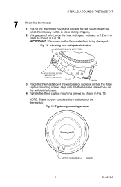
.... Using a pencil point, slide the heat anticipator indicator to 1.2 on the wallplate/subbase. 4. IMPORTANT: This prevents the thermostat from being damaged. Fig. 14. CT87A,B,J ROUND® THERMOSTAT 7 Mount the thermostat 1. NOTE: These screws complete the installation of the thermostat. CAPTIVE SCREWS (3) M20227 9 69-0274-6 Tightening mounting screws. HEAT ANTICIPATOR INDICATOR 1.2 .6 .5 .4 .3 .2 HOLE SUITABLE FOR PENCIL POINT TO...
.... Using a pencil point, slide the heat anticipator indicator to 1.2 on the wallplate/subbase. 4. IMPORTANT: This prevents the thermostat from being damaged. Fig. 14. CT87A,B,J ROUND® THERMOSTAT 7 Mount the thermostat 1. NOTE: These screws complete the installation of the thermostat. CAPTIVE SCREWS (3) M20227 9 69-0274-6 Tightening mounting screws. HEAT ANTICIPATOR INDICATOR 1.2 .6 .5 .4 .3 .2 HOLE SUITABLE FOR PENCIL POINT TO...


