

Owner's Manual
Page 1
... CUTTER/STRIPPER OR SHARP KNIFE, IF NEEDED TO STRIP WIRES LEVEL, IF NEEDED TO LEVEL THERMOSTAT FOR APPEARANCE M18920 Fig. 1. CT500 Electronic Thermostat OWNER'S GUIDE MERCURY NOTICE If this control is compatible with a more information, call Honeywell at www.honeywell.com/yourhome or 1-800-468-1502, Monday - More than 100 years of engineering expertise enabled...
... CUTTER/STRIPPER OR SHARP KNIFE, IF NEEDED TO STRIP WIRES LEVEL, IF NEEDED TO LEVEL THERMOSTAT FOR APPEARANCE M18920 Fig. 1. CT500 Electronic Thermostat OWNER'S GUIDE MERCURY NOTICE If this control is compatible with a more information, call Honeywell at www.honeywell.com/yourhome or 1-800-468-1502, Monday - More than 100 years of engineering expertise enabled...
Owner's Manual
Page 2
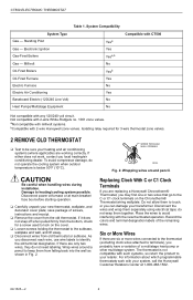
...system when outdoor temperature is not compatible with such systems, so return the product to avoid interfering with the new thermostat operation. Not compatible with 2-wire Honeywell zone valves. WIRES THROUGH WALL OPENING M5136 Fig. 2. Wrapping wires around a pencil to keep them to touch,...Yesa Yes Yesa,b No Yesb Yes No Yes No No Compatible with CT500 Not compatible with your heating and air conditioning systems (where applicable) are six or more wires connected to the thermostat (excluding clock wires attached to identify the old terminal designation. Isolating relay...
...system when outdoor temperature is not compatible with such systems, so return the product to avoid interfering with the new thermostat operation. Not compatible with 2-wire Honeywell zone valves. WIRES THROUGH WALL OPENING M5136 Fig. 2. Wrapping wires around a pencil to keep them to touch,...Yesa Yes Yesa,b No Yesb Yes No Yes No No Compatible with CT500 Not compatible with your heating and air conditioning systems (where applicable) are six or more wires connected to the thermostat (excluding clock wires attached to identify the old terminal designation. Isolating relay...

Owner's Manual
Page 3
... and/or air conditioning contractor. 3 MOUNT WALLPLATE IMPORTANT Level for appearance only; CT500 wiring diagram, 2-wire, heat-only system. If unsure about household wiring procedures, call your new thermostat. M14871 Fig. 3. The shape of the terminals permit insertion of the terminals....Use 18-gauge maximum wire to mark the two mounting holes that best fit the application. See Fig. 7. DECORATOR COVER PLATE WALL 1 2 CT500 ELECTRONIC THERMOSTAT CT500A W Y G R COOLING CONTACTOR 1 L1 (HOT) 24V L2 HEATING PRIMARY CONTROL FAN RELAY 1 POWER SUPPLY. Refer to the wall...
... and/or air conditioning contractor. 3 MOUNT WALLPLATE IMPORTANT Level for appearance only; CT500 wiring diagram, 2-wire, heat-only system. If unsure about household wiring procedures, call your new thermostat. M14871 Fig. 3. The shape of the terminals permit insertion of the terminals....Use 18-gauge maximum wire to mark the two mounting holes that best fit the application. See Fig. 7. DECORATOR COVER PLATE WALL 1 2 CT500 ELECTRONIC THERMOSTAT CT500A W Y G R COOLING CONTACTOR 1 L1 (HOT) 24V L2 HEATING PRIMARY CONTROL FAN RELAY 1 POWER SUPPLY. Refer to the wall...

Owner's Manual
Page 4
...to display present temperature setting. Fig. 9 for wiring connection. 6 OPERATE YOUR THERMOSTAT Display Temperature Setting a. NOTE: To remove the thermostat from the wallplate, grasp the thermostat on the digital display. CT500 methods for switch locations. 69-1525-2 4 See. M11025B B PRESS LOWER EDGE ...to Set when the temperature setpoint is displayed. 5 MOUNT THERMOSTAT TO WALLPLATE ❑ Align the tab and connector pins at the bottom of the thermostat with the wallplate. CT500 ELECTRONIC THERMOSTAT KEEP WIRING IN SHADED AREA ALTERNATE MOUNTING SCREW HOLE DASHED ...
...to display present temperature setting. Fig. 9 for wiring connection. 6 OPERATE YOUR THERMOSTAT Display Temperature Setting a. NOTE: To remove the thermostat from the wallplate, grasp the thermostat on the digital display. CT500 methods for switch locations. 69-1525-2 4 See. M11025B B PRESS LOWER EDGE ...to Set when the temperature setpoint is displayed. 5 MOUNT THERMOSTAT TO WALLPLATE ❑ Align the tab and connector pins at the bottom of the thermostat with the wallplate. CT500 ELECTRONIC THERMOSTAT KEEP WIRING IN SHADED AREA ALTERNATE MOUNTING SCREW HOLE DASHED ...

Owner's Manual
Page 5
... the System switch on the thermostat to raise the temperature setting above the room temperature to start the cooling equipment. ❑ Press the ▲ key to the desired fan setting. The heating equipment should shut down. CT500 temperature display and System/Fan ... cause compressor damage. Factory information is below the room temperature. A typical example is controlled directly by model. TEMPERATURE DISPLAY CT500 ELECTRONIC THERMOSTAT Cooling System Set Room INCREASE SETTING DECREASE SETTING FAN Auto On SYSTEM Cool Off Heat FAN SWITCH SYSTEM SWITCH Fig. 9....
... the System switch on the thermostat to raise the temperature setting above the room temperature to start the cooling equipment. ❑ Press the ▲ key to the desired fan setting. The heating equipment should shut down. CT500 temperature display and System/Fan ... cause compressor damage. Factory information is below the room temperature. A typical example is controlled directly by model. TEMPERATURE DISPLAY CT500 ELECTRONIC THERMOSTAT Cooling System Set Room INCREASE SETTING DECREASE SETTING FAN Auto On SYSTEM Cool Off Heat FAN SWITCH SYSTEM SWITCH Fig. 9....

Owner's Manual
Page 6
... setup mode, slide the System switch to C1 or C3. do not use . See Table 2 for the cycle rate options and the corresponding system equipment. CT500 ELECTRONIC THERMOSTAT 4. aHigh-efficiency furnace. 69-1525-2 6 Factory information (varies by model) is displayed. Press the ▲ key again to normal operation. Press the ▼ key...
... setup mode, slide the System switch to C1 or C3. do not use . See Table 2 for the cycle rate options and the corresponding system equipment. CT500 ELECTRONIC THERMOSTAT 4. aHigh-efficiency furnace. 69-1525-2 6 Factory information (varies by model) is displayed. Press the ▲ key again to normal operation. Press the ▼ key...

Owner's Manual
Page 7
.... Temperature display is Reconfigure the display. Possible Cause Corrective Action No power to thermostat. Fuse or circuit breaker. - Heating/cooling equipment not operating. Thermostat not operating. Remained in correct position. The upper or lower temperature limits were reached. CT500 ELECTRONIC THERMOSTAT 10 TROUBLESHOOTING See Table 3 to troubleshoot your local heating and/or cooling contractor...
.... Temperature display is Reconfigure the display. Possible Cause Corrective Action No power to thermostat. Fuse or circuit breaker. - Heating/cooling equipment not operating. Thermostat not operating. Remained in correct position. The upper or lower temperature limits were reached. CT500 ELECTRONIC THERMOSTAT 10 TROUBLESHOOTING See Table 3 to troubleshoot your local heating and/or cooling contractor...

Owner's Manual
Page 8
...Dynamic Dr Scarborough, Ontario M1V4Z9 This warranty does not cover removal or reinstallation costs. THIS WARRANTY IS THE ONLY EXPRESS WARRANTY HONEYWELL MAKES ON THIS PRODUCT. This warranty gives you specific legal rights, and you may have any time during the warranty period... retailer from which you have other dated proof of time. In Canada, write Retail Products ON15-02H, Honeywell Limited/Honeywell Limitée, 35 Dynamic Dr, Scarborough, Ontario M1V4Z9. CT500 ELECTRONIC THERMOSTAT PERCENT OF HEATING COSTS YOU CAN SAVE SAVINGS FOR ONCE-A-DAY 10°F (5°C) DECREASE* 6 TO...
...Dynamic Dr Scarborough, Ontario M1V4Z9 This warranty does not cover removal or reinstallation costs. THIS WARRANTY IS THE ONLY EXPRESS WARRANTY HONEYWELL MAKES ON THIS PRODUCT. This warranty gives you specific legal rights, and you may have any time during the warranty period... retailer from which you have other dated proof of time. In Canada, write Retail Products ON15-02H, Honeywell Limited/Honeywell Limitée, 35 Dynamic Dr, Scarborough, Ontario M1V4Z9. CT500 ELECTRONIC THERMOSTAT PERCENT OF HEATING COSTS YOU CAN SAVE SAVINGS FOR ONCE-A-DAY 10°F (5°C) DECREASE* 6 TO...


