
Owner's Manual
Page 1
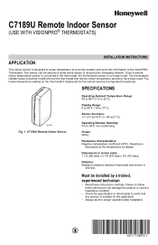
... these instructions can be modified to verify that remote indoor temperature sensor(s) have been used. Failure to follow these instructions carefully. C7189U Remote Indoor Sensor (USE WITH VISIONPRO® THERMOSTATS) APPLICATION INSTALLATION INSTRUCTIONS This indoor sensor is designed to sense temperature at 21°C) Operating Relative Humidity: 5% to the thermostat, the thermostat...
... these instructions can be modified to verify that remote indoor temperature sensor(s) have been used. Failure to follow these instructions carefully. C7189U Remote Indoor Sensor (USE WITH VISIONPRO® THERMOSTATS) APPLICATION INSTALLATION INSTRUCTIONS This indoor sensor is designed to sense temperature at 21°C) Operating Relative Humidity: 5% to the thermostat, the thermostat...
Owner's Manual
Page 2
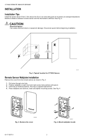
..., insert and tighten mounting screws. M24056 Fig. 3. Mount wallplate to wall. 69-1710EFS-1 2 Remote Sensor Wallplate Installation Remove the cover from the remote sensor as shown in supplied wall anchors. 4. C7189U REMOTE INDOOR SENSOR INSTALLATION Installation Tips Install the sensor about 5 feet (1.5m) above the floor in an area with pencil. 3. CAUTION Electrical Hazard Can...
..., insert and tighten mounting screws. M24056 Fig. 3. Mount wallplate to wall. 69-1710EFS-1 2 Remote Sensor Wallplate Installation Remove the cover from the remote sensor as shown in supplied wall anchors. 4. C7189U REMOTE INDOOR SENSOR INSTALLATION Installation Tips Install the sensor about 5 feet (1.5m) above the floor in an area with pencil. 3. CAUTION Electrical Hazard Can...
Owner's Manual
Page 3
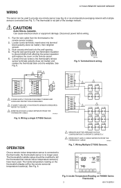
...onto the wallplate. C7189 3 2 Y2 Y2 RC R 1 W R W2 Y C S1 G S2 C 1 POWER SUPPLY. Wiring Multiple C7189U Sensors. . TUE FAN CHANGE FILTER UV LAMP HUMIDIFIER PAD Inside Set To AUTO Heat On SYSTEM Following Schedule HEAT AM SCHED HOLD CLOCK SCREEN MORE... wiring. Push excess wire back into terminal block (polarity does not matter), then retighten screws. 3. M19972A Fig. 6. The thermostat's installer setup should be the remote sensor(s) temperature location(s). CAUTION ELECTRICAL HAZARD. See Fig. 8. 1 SENSORS MUST BE ARRANGED IN THIS CONFIGURATION ...
...onto the wallplate. C7189 3 2 Y2 Y2 RC R 1 W R W2 Y C S1 G S2 C 1 POWER SUPPLY. Wiring Multiple C7189U Sensors. . TUE FAN CHANGE FILTER UV LAMP HUMIDIFIER PAD Inside Set To AUTO Heat On SYSTEM Following Schedule HEAT AM SCHED HOLD CLOCK SCREEN MORE... wiring. Push excess wire back into terminal block (polarity does not matter), then retighten screws. 3. M19972A Fig. 6. The thermostat's installer setup should be the remote sensor(s) temperature location(s). CAUTION ELECTRICAL HAZARD. See Fig. 8. 1 SENSORS MUST BE ARRANGED IN THIS CONFIGURATION ...


