
Owner's Manual
Page 1
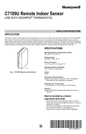
... modified to tell the thermostat that this information to the VisionPRO Thermostat. Once a remote indoor temperature sensor is connected to follow these instructions carefully. SPECIFICATIONS M24055 Fig. 1. Resistance Characteristics: Negative temperature coefficient (NTC). Dimensions in this booklet to 95% non-condensing. C7189U Remote Indoor Sensor Operating Ambient Temperature Range: 45 to 88°F (7.2 to 37°C). Display Range: 0 to 99...
... modified to tell the thermostat that this information to the VisionPRO Thermostat. Once a remote indoor temperature sensor is connected to follow these instructions carefully. SPECIFICATIONS M24055 Fig. 1. Resistance Characteristics: Negative temperature coefficient (NTC). Dimensions in this booklet to 95% non-condensing. C7189U Remote Indoor Sensor Operating Ambient Temperature Range: 45 to 88°F (7.2 to 37°C). Display Range: 0 to 99...
Owner's Manual
Page 2
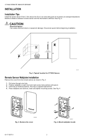
... NO NO 5 FEET (1.5 METERS) NO M24115 Fig. 2. Drill holes at average temperature. Place wallplate over anchors, insert and tighten mounting screws. M24057 Fig. 4. Typical location for C7189U Sensor. Pull wires through wire hole. 2. Remove the cover. C7189U REMOTE INDOOR SENSOR INSTALLATION Installation Tips Install the sensor about 5 feet (1.5m) above the floor in an area with pencil. 3. Maximum...
... NO NO 5 FEET (1.5 METERS) NO M24115 Fig. 2. Drill holes at average temperature. Place wallplate over anchors, insert and tighten mounting screws. M24057 Fig. 4. Typical location for C7189U Sensor. Pull wires through wire hole. 2. Remove the cover. C7189U REMOTE INDOOR SENSOR INSTALLATION Installation Tips Install the sensor about 5 feet (1.5m) above the floor in an area with pencil. 3. Maximum...
Owner's Manual
Page 3
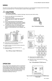
...The Inside temperature reading on TH8000 Series Thermostat. 3 69-1710EFS-1 C7189U REMOTE INDOOR SENSOR WIRING The sensor can be used to provide one remote sensor (see... Fig. 7). Push excess wire back into terminal block (polarity does not matter), then retighten screws. 3. Connect the two wires to the remote sensor location. 2. W2 1 1 2 S2 C7189 C7189 C7189 C7189 Y2 W2 1 1 2 2 C7189 C7189 C7189 C7189 C7189 C7189 C7189 C7189 C7189 OPERATION Once a remote indoor temperature sensor...
...The Inside temperature reading on TH8000 Series Thermostat. 3 69-1710EFS-1 C7189U REMOTE INDOOR SENSOR WIRING The sensor can be used to provide one remote sensor (see... Fig. 7). Push excess wire back into terminal block (polarity does not matter), then retighten screws. 3. Connect the two wires to the remote sensor location. 2. W2 1 1 2 S2 C7189 C7189 C7189 C7189 Y2 W2 1 1 2 2 C7189 C7189 C7189 C7189 C7189 C7189 C7189 C7189 C7189 OPERATION Once a remote indoor temperature sensor...
Owner's Manual
Page 4
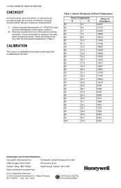
...://yourhome.honeywell.com ® U.S. Rev. 10-05 Use an accurate thermometer (+/-1ºF[0.5ºC]) measure the temperature at Room Temperature. Patents Pending. 69-1710EFS-1 M.S. Verify the sensor accuracy with the temperature/resistance in the field. Use an ohmmeter to absorb the air moving through the room for a minimum of twenty minutes before taking a resistance measurement. 1. C7189U REMOTE INDOOR SENSOR CHECKOUT...
...://yourhome.honeywell.com ® U.S. Rev. 10-05 Use an accurate thermometer (+/-1ºF[0.5ºC]) measure the temperature at Room Temperature. Patents Pending. 69-1710EFS-1 M.S. Verify the sensor accuracy with the temperature/resistance in the field. Use an ohmmeter to absorb the air moving through the room for a minimum of twenty minutes before taking a resistance measurement. 1. C7189U REMOTE INDOOR SENSOR CHECKOUT...


