
Owner's Manual
Page 1
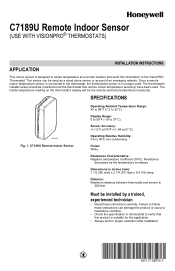
... in this information to the VisionPRO Thermostat. Must be the remote sensor(s) temperature location(s). Sensor Accuracy: +/-1.5°F at 70°F (+/-.84 at a remote location and send this booklet to verify that remote indoor temperature sensor(s) have been used . C7189U Remote Indoor Sensor (USE WITH VISIONPRO® THERMOSTATS) APPLICATION INSTALLATION INSTRUCTIONS This indoor sensor is designed to sense temperature at 21°C) Operating Relative...
... in this information to the VisionPRO Thermostat. Must be the remote sensor(s) temperature location(s). Sensor Accuracy: +/-1.5°F at 70°F (+/-.84 at a remote location and send this booklet to verify that remote indoor temperature sensor(s) have been used . C7189U Remote Indoor Sensor (USE WITH VISIONPRO® THERMOSTATS) APPLICATION INSTALLATION INSTRUCTIONS This indoor sensor is designed to sense temperature at 21°C) Operating Relative...
Owner's Manual
Page 2
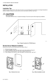
Maximum distance between remote sensor and the thermostat is 200 feet. CAUTION Electrical Hazard Can cause electrical shock or equipment damage. YES NO NO 5 FEET (1.5 METERS) ... 4. M24056 Fig. 3. Typical location for C7189U Sensor. Mount wallplate to wall. 69-1710EFS-1 2 Remove the cover. C7189U REMOTE INDOOR SENSOR INSTALLATION Installation Tips Install the sensor about 5 feet (1.5m) above the floor in supplied wall anchors. 4. Pull wires through wire hole. 2. Remote Sensor Wallplate Installation Remove the cover from the remote sensor as shown in Fig. 3. 1. Place ...
Maximum distance between remote sensor and the thermostat is 200 feet. CAUTION Electrical Hazard Can cause electrical shock or equipment damage. YES NO NO 5 FEET (1.5 METERS) ... 4. M24056 Fig. 3. Typical location for C7189U Sensor. Mount wallplate to wall. 69-1710EFS-1 2 Remove the cover. C7189U REMOTE INDOOR SENSOR INSTALLATION Installation Tips Install the sensor about 5 feet (1.5m) above the floor in supplied wall anchors. 4. Pull wires through wire hole. 2. Remote Sensor Wallplate Installation Remove the cover from the remote sensor as shown in Fig. 3. 1. Place ...
Owner's Manual
Page 3
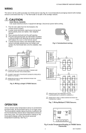
... REQUIRED, REFER TO FIGURE 7. 3 WIRES MUST HAVE A CABLE SEPARATE FROM THE THERMOSTAT CABLE. CAUTION ELECTRICAL HAZARD. Wiring Multiple C7189U Sensors. . C7189U REMOTE INDOOR SENSOR WIRING The sensor can be used . The thermostat is no longer used to the thermostat's remote sensor terminals (polarity does not matter) and replace the thermostat back onto the wallplate. Terminal block wiring. TUE FAN...
... REQUIRED, REFER TO FIGURE 7. 3 WIRES MUST HAVE A CABLE SEPARATE FROM THE THERMOSTAT CABLE. CAUTION ELECTRICAL HAZARD. Wiring Multiple C7189U Sensors. . C7189U REMOTE INDOOR SENSOR WIRING The sensor can be used . The thermostat is no longer used to the thermostat's remote sensor terminals (polarity does not matter) and replace the thermostat back onto the wallplate. Terminal block wiring. TUE FAN...
Owner's Manual
Page 4
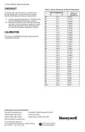
...;e 1985 Douglas Drive North 35 Dynamic Drive Golden Valley, MN 55422 Scarborough, Ontario M1V 4Z9 http://yourhome.honeywell.com ® U.S. C7189U REMOTE INDOOR SENSOR CHECKOUT For best results, allow the sensor to measure the resistance across the sensor. Verify the sensor accuracy with the temperature/resistance in the field. Room Temperature °F °C 40 4.4 42 5.6 44 6.7 46 7.8 48...
...;e 1985 Douglas Drive North 35 Dynamic Drive Golden Valley, MN 55422 Scarborough, Ontario M1V 4Z9 http://yourhome.honeywell.com ® U.S. C7189U REMOTE INDOOR SENSOR CHECKOUT For best results, allow the sensor to measure the resistance across the sensor. Verify the sensor accuracy with the temperature/resistance in the field. Room Temperature °F °C 40 4.4 42 5.6 44 6.7 46 7.8 48...


