
Owner's Manual
Page 1
Rev. 9-94 ©Honeywell Inc. 1994 Form Number 69-0643-1 M3375 T8190A/191108AJ, Q682 Heating or Cooling Thermostat and Wallplate or Heating/Cooling Thermostat and Subbase D.F.
Rev. 9-94 ©Honeywell Inc. 1994 Form Number 69-0643-1 M3375 T8190A/191108AJ, Q682 Heating or Cooling Thermostat and Wallplate or Heating/Cooling Thermostat and Subbase D.F.
Owner's Manual
Page 2
Welcome... If this control is your assurance of its useful life. Your new thermostat will automatically lower and raise the temperature in a sealed tube. The Honeywell name is replacing a control that contains mercury in a sealed tube, do not place your home one or more times every 24 ... control contains mercury in your old control in the trash. Do not place control in a sealed tube. 2 69-0643-1 Contact your new Honeywell thermostat. Read this control, or of energy savings with your local waste management authority for years to come. to the world of an old control...
Welcome... If this control is your assurance of its useful life. Your new thermostat will automatically lower and raise the temperature in a sealed tube. The Honeywell name is replacing a control that contains mercury in a sealed tube, do not place your home one or more times every 24 ... control contains mercury in your old control in the trash. Do not place control in a sealed tube. 2 69-0643-1 Contact your new Honeywell thermostat. Read this control, or of energy savings with your local waste management authority for years to come. to the world of an old control...
Owner's Manual
Page 3
Table of Contents Page Features of Your Thermostat ...4 Setting the Temperature ...7 Inserting Timer Batteries ...8 Setting the Timer ...9 Programming ...10 Setting Subbase Switches ...13 Troubleshooting ...14 Servicing the Thermostat ...22 Cycle Rate Adjustment ...22 Thermometer Adjustment ...23 Warranty ...27 3 69-0643-1
Table of Contents Page Features of Your Thermostat ...4 Setting the Temperature ...7 Inserting Timer Batteries ...8 Setting the Timer ...9 Programming ...10 Setting Subbase Switches ...13 Troubleshooting ...14 Servicing the Thermostat ...22 Cycle Rate Adjustment ...22 Thermometer Adjustment ...23 Warranty ...27 3 69-0643-1
Owner's Manual
Page 4
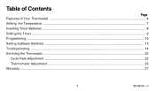
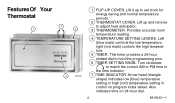
.... 4 TEMPERATURE SETTING LEVERS. Also indicates time on program index wheel. Lift it up and remove to set clock for energy saving and normal temperature periods. 2 THERMOSTAT COVER. Lift up to adjust heat anticipator. 3 THERMOMETER. Turn clockwise to match the correct AM or PM time to hold the programming pins. 6 TIMER SETTING... KNOB. Arrow head (triangle shape) indicates low (blue) temperature setting or high (red) temperature setting in control on 24-hour dial. 4 69-0643-1 FeaturesOf Your Thermostat 4 1 2 3 M7349 1 FLIP-UP COVER.
.... 4 TEMPERATURE SETTING LEVERS. Also indicates time on program index wheel. Lift it up and remove to set clock for energy saving and normal temperature periods. 2 THERMOSTAT COVER. Lift up to adjust heat anticipator. 3 THERMOMETER. Turn clockwise to match the correct AM or PM time to hold the programming pins. 6 TIMER SETTING... KNOB. Arrow head (triangle shape) indicates low (blue) temperature setting or high (red) temperature setting in control on 24-hour dial. 4 69-0643-1 FeaturesOf Your Thermostat 4 1 2 3 M7349 1 FLIP-UP COVER.
Owner's Manual
Page 6
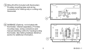
See Setting Subbase Switches section for heating/cooling thermostat. ordered separately.) Provides mounting base, wiring connections and manual switching control for additional information. 16 6 M2421 R G FAN ON AUTO O B W Y HEAT COOL OFF M 719 69-0643-1 15 WALLPLATE (Included with thermostat.) Provides mounting base and wiring connections for heating-only or cooling-only thermostat. 15 16 SUBBASE (Optional, not included with thermostat;
See Setting Subbase Switches section for heating/cooling thermostat. ordered separately.) Provides mounting base, wiring connections and manual switching control for additional information. 16 6 M2421 R G FAN ON AUTO O B W Y HEAT COOL OFF M 719 69-0643-1 15 WALLPLATE (Included with thermostat.) Provides mounting base and wiring connections for heating-only or cooling-only thermostat. 15 16 SUBBASE (Optional, not included with thermostat;
Owner's Manual
Page 8
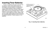
... two new AAA alkaline batteries. INSTALL WITH POSITIVE ENDS UP M8585 Fig. 2-Inserting timer batteries. 8 69-0643-1 BATTERY LOCATION FOR (2) AAA BATTERIES; Install batteries in thermostat as shown in Fig. 2. Properly dispose of old batteries. We recommend Energizer® batteries. Inserting Timer Batteries Power is interrupted when using a 24 Vac powering...
... two new AAA alkaline batteries. INSTALL WITH POSITIVE ENDS UP M8585 Fig. 2-Inserting timer batteries. 8 69-0643-1 BATTERY LOCATION FOR (2) AAA BATTERIES; Install batteries in thermostat as shown in Fig. 2. Properly dispose of old batteries. We recommend Energizer® batteries. Inserting Timer Batteries Power is interrupted when using a 24 Vac powering...
Owner's Manual
Page 9
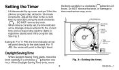
... ARROW Fig. 3-Setting the timer. 69-0643-1 When Daylight Saving Time ends, move the knob carefully in 10-minute increments. Setting the Timer ■ Lift thermostat flip-up cover and you'll find the 24-hour program dial, slotted in a clockwise direction one hour. the knob carefully in a clockwise direction 23...
... ARROW Fig. 3-Setting the timer. 69-0643-1 When Daylight Saving Time ends, move the knob carefully in 10-minute increments. Setting the Timer ■ Lift thermostat flip-up cover and you'll find the 24-hour program dial, slotted in a clockwise direction one hour. the knob carefully in a clockwise direction 23...
Owner's Manual
Page 10
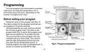
...for the program pins that can be inserted at 10-minute intervals. ■ Three red and three blue program pins are included with your thermostat to automatically lower and raise the temperature one or more times every 24 hours, depending on the number of program pins used. The dial ...is inserted at 6:00 AM for the program pins that can program your thermostat. A red pin is slotted for high PROGRAM PINS THERMOSTAT COVER PROGRAM PIN SLOT PROGRAM INDEX WHEEL TIME INDICATOR ARROW PROGRAM PIN STORAGE M7348 Fig. 4-Program components. 10 69-...
...for the program pins that can be inserted at 10-minute intervals. ■ Three red and three blue program pins are included with your thermostat to automatically lower and raise the temperature one or more times every 24 hours, depending on the number of program pins used. The dial ...is inserted at 6:00 AM for the program pins that can program your thermostat. A red pin is slotted for high PROGRAM PINS THERMOSTAT COVER PROGRAM PIN SLOT PROGRAM INDEX WHEEL TIME INDICATOR ARROW PROGRAM PIN STORAGE M7348 Fig. 4-Program components. 10 69-...
Owner's Manual
Page 13
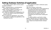
...To switch positions, use thumb or index finger to slide the lever to the desired position. Cooling system is controlled by the thermostat. For proper circuit operation, switch lever must stop in heating and cooling. COOL-Cooling system is off . Heating system is controlled by the... thermostat in detent over desired function indicator mark. 13 69-0643-1 In heating-only applications, only heating will operate. ON-In cooling-...
...To switch positions, use thumb or index finger to slide the lever to the desired position. Cooling system is controlled by the thermostat. For proper circuit operation, switch lever must stop in heating and cooling. COOL-Cooling system is off . Heating system is controlled by the... thermostat in detent over desired function indicator mark. 13 69-0643-1 In heating-only applications, only heating will operate. ON-In cooling-...
Owner's Manual
Page 14
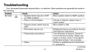
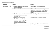
Furnace power switch may be in OFF or COOL position. - Other. 14 Action Move system switch to furnace. Fuse or circuit breaker. - Thermostat connections. - Turn off power to HEAT position. Problem No heat. 2 Check - Move switch to furnace manufacturer instructions. Turn on power. Firmly tighten all terminal screws. ... may be traced to the following. Pilot flame may be OFF. - Most problems can generally be out. - Relight pilot flame according to ON . Troubleshooting Your Honeywell thermostat requires little or no attention.
Furnace power switch may be in OFF or COOL position. - Other. 14 Action Move system switch to furnace. Fuse or circuit breaker. - Thermostat connections. - Turn off power to HEAT position. Problem No heat. 2 Check - Move switch to furnace manufacturer instructions. Turn on power. Firmly tighten all terminal screws. ... may be traced to the following. Pilot flame may be OFF. - Most problems can generally be out. - Relight pilot flame according to ON . Troubleshooting Your Honeywell thermostat requires little or no attention.
Owner's Manual
Page 15
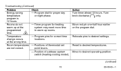
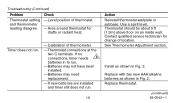
... position. (continued) 15 69-0643-1 Program dial for correct time locations. - Move to desired temperatures. Positions of subbase system switch (heating-cooling model). Position of thermostat set point levers. - Timer program for heating system may need more time to desired settings. Check - Relocate pins to warm up at the programmed time...
... position. (continued) 15 69-0643-1 Program dial for correct time locations. - Move to desired temperatures. Positions of subbase system switch (heating-cooling model). Position of thermostat set point levers. - Timer program for heating system may need more time to desired settings. Check - Relocate pins to warm up at the programmed time...
Owner's Manual
Page 16
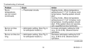
... location.) Action Heating mode-Move temperature setting levers 5° F [3° C] above room temperature. Heating system should start . Increase anticipator setting by 0.05 (e.g., 0.45 to 0.45). Thermostat circuits. for anticipator location.) Burner-on time too short. - Observe burner operation. (continued) 16 69-0643-1 Decrease anticipator setting by 0.05 (e.g., 0.4 to 0.4). Check - If the...
... location.) Action Heating mode-Move temperature setting levers 5° F [3° C] above room temperature. Heating system should start . Increase anticipator setting by 0.05 (e.g., 0.45 to 0.45). Thermostat circuits. for anticipator location.) Burner-on time too short. - Observe burner operation. (continued) 16 69-0643-1 Decrease anticipator setting by 0.05 (e.g., 0.4 to 0.4). Check - If the...
Owner's Manual
Page 17
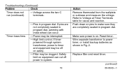
... service technician for correct terminal hookups. Located outdoors and may be turned off power to cooling system. Other. 17 Action Move switch to ON position. Thermostat connections. Move to COOL position. Firmly tighten all terminal screws. - Check for assistance. (continued) 69-0643-1 Troubleshooting (Continued) Problem No cooling. 1 Check - Condenser switch position...
... service technician for correct terminal hookups. Located outdoors and may be turned off power to cooling system. Other. 17 Action Move switch to ON position. Thermostat connections. Move to COOL position. Firmly tighten all terminal screws. - Check for assistance. (continued) 69-0643-1 Troubleshooting (Continued) Problem No cooling. 1 Check - Condenser switch position...
Owner's Manual
Page 18
... timer needs 3 batteries in to run . - Replace with two new AAA alkaline batteries as shown in Fig. 2. Use a spirit level. Thermostat should be about 5 ft [1.5m] above floor on an inside wall. Contact qualified service technician for drafts or radiant heat. Batteries may not ...have been installed. - Replace thermostat. (continued) 69-0643-1 Check - Install as shown in Fig. 2. Calibration of location. If new batteries are installed and timer still ...
... timer needs 3 batteries in to run . - Replace with two new AAA alkaline batteries as shown in Fig. 2. Use a spirit level. Thermostat should be about 5 ft [1.5m] above floor on an inside wall. Contact qualified service technician for drafts or radiant heat. Batteries may not ...have been installed. - Replace thermostat. (continued) 69-0643-1 Check - Install as shown in Fig. 2. Calibration of location. If new batteries are installed and timer still ...
Owner's Manual
Page 19
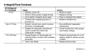
If pins are completely seated in Fig. 2. Filter may be off power to system. 19 Action Remove thermostat from the wallplate or subbase and measure the voltage. Refer to power timer, or install backup batteries as shown in program dial. Pins in program ...
If pins are completely seated in Fig. 2. Filter may be off power to system. 19 Action Remove thermostat from the wallplate or subbase and measure the voltage. Refer to power timer, or install backup batteries as shown in program dial. Pins in program ...
Owner's Manual
Page 21
Action - Replace wiring. - Replace transformer. - Spring fingers on thermostat not making proper contact with proper secondary voltage. - Replace thermostat. 21 69-0643-1 System power off. - Short in timer power supply wiring. - Transformer supplying power is inadequate. - Timer has failed. Use additional (separate) transformer. - Install ...
Action - Replace wiring. - Replace transformer. - Spring fingers on thermostat not making proper contact with proper secondary voltage. - Replace thermostat. 21 69-0643-1 System power off. - Short in timer power supply wiring. - Transformer supplying power is inadequate. - Timer has failed. Use additional (separate) transformer. - Install ...

Owner's Manual
Page 22
ANTICIPATOR SCALEPLATE ANTICIPATOR SETTING LEVER M7317 Fig. 6-Heat anticipator setting. 22 69-0643-1 Observe the heating system operation after each adjustment. Servicing the Thermostat Cycle Rate Adjustment The equipment should cycle on and off just enough to keep the room temperature close to cycle the heating system too fast or too slow, adjust the cycle rate by moving the anticipator setting lever one indicator mark at a time (Fig. 6). NOTE: Most hot water systems require a setting of 1.2A. If the thermostat seems to the temperature lever settings.
ANTICIPATOR SCALEPLATE ANTICIPATOR SETTING LEVER M7317 Fig. 6-Heat anticipator setting. 22 69-0643-1 Observe the heating system operation after each adjustment. Servicing the Thermostat Cycle Rate Adjustment The equipment should cycle on and off just enough to keep the room temperature close to cycle the heating system too fast or too slow, adjust the cycle rate by moving the anticipator setting lever one indicator mark at a time (Fig. 6). NOTE: Most hot water systems require a setting of 1.2A. If the thermostat seems to the temperature lever settings.

Owner's Manual
Page 23
... thermometer of known accuracy. If the setpoint lever and the thermometer reading do not agree, follow the procedure below. Remove thermostat cover and open the flip-up cover. Replace thermostat cover and put the system into operation. THERMOMETER SLOT BACKSIDE OF FLIP-UP COVER INSERT AND TURN SCREWDRIVER M1810 Fig. 7-Thermometer... in Fig. 7, and turn it has been dropped or mishandled. Be careful not to sense area temperature; then compare the readings. Set the thermostat cover on it. If the readings are the same, replace the cover and put the system into operation.
... thermometer of known accuracy. If the setpoint lever and the thermometer reading do not agree, follow the procedure below. Remove thermostat cover and open the flip-up cover. Replace thermostat cover and put the system into operation. THERMOMETER SLOT BACKSIDE OF FLIP-UP COVER INSERT AND TURN SCREWDRIVER M1810 Fig. 7-Thermometer... in Fig. 7, and turn it has been dropped or mishandled. Be careful not to sense area temperature; then compare the readings. Set the thermostat cover on it. If the readings are the same, replace the cover and put the system into operation.
Owner's Manual
Page 24
If you have questions regarding the installation and programming of your Honeywell thermostat, please visit our web site at www.honeywell.com/yourhome or call the 24-hour automated information line at 1-800-468-1502. 24 69-0643-1
If you have questions regarding the installation and programming of your Honeywell thermostat, please visit our web site at www.honeywell.com/yourhome or call the 24-hour automated information line at 1-800-468-1502. 24 69-0643-1


