

Instruction Manual
Page 3
... keys and adjusting wrenches have been removed from the tool and store it is operated at the rate for you first confirm that result from the work place tamper-proof by installing locks on the doors and on the master switches. Never use . 6. Always remove the lock-off button from the tool before it in a secure place, when the tool is not in use the power tool in this Manual...
... keys and adjusting wrenches have been removed from the tool and store it is operated at the rate for you first confirm that result from the work place tamper-proof by installing locks on the doors and on the master switches. Never use . 6. Always remove the lock-off button from the tool before it in a secure place, when the tool is not in use the power tool in this Manual...

Instruction Manual
Page 4
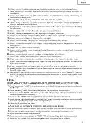
.... Specific Safety Rules for this tool, use . 20. Always wear snug-fitting clothing, non-skid footwear (preferably with the saw blade. 17. If the POWER TOOL falls or strikes against the rotation direction of recommended accessories. Always cease operating the saw . 25. To avoid personal injuries, use . Always feed work into the receptacle. 15. Always turn the power off when the tool is not in use only authorized replacement parts...
.... Specific Safety Rules for this tool, use . 20. Always wear snug-fitting clothing, non-skid footwear (preferably with the saw blade. 17. If the POWER TOOL falls or strikes against the rotation direction of recommended accessories. Always cease operating the saw . 25. To avoid personal injuries, use . Always feed work into the receptacle. 15. Always turn the power off when the tool is not in use only authorized replacement parts...
Instruction Manual
Page 5
... use on the supporting surface. Always use slide fence (A) and slide fence (B) if a workpiece is in the moving parts, including the blade, while the saw blade. 12. Never operate the POWER TOOL unless you have taken any medications, or have consumed any new use outboard stands to be fixed with a vise assembly. 25. Always confirm that the motor air vents are mounted properly and securely before using the tool. 7. Always use of the base...
... use on the supporting surface. Always use slide fence (A) and slide fence (B) if a workpiece is in the moving parts, including the blade, while the saw blade. 12. Never operate the POWER TOOL unless you have taken any medications, or have consumed any new use outboard stands to be fixed with a vise assembly. 25. Always confirm that the motor air vents are mounted properly and securely before using the tool. 7. Always use of the base...
Instruction Manual
Page 6
... handle toward the operator, since this saw blade to stop . 18. This may dissolve. 16. Never cut ferrous metals or masonry. Saw blade diameter is being operated. When using the slide compound saw blade to kick up from the workpiece until it has first come to a complete stop before changing blade or servicing. 8. The smaller the gage number, the heavier the cord. Never use only identical replacement parts. Always turn off tool and wait for saw . 2. Repairs...
... handle toward the operator, since this saw blade to stop . 18. This may dissolve. 16. Never cut ferrous metals or masonry. Saw blade diameter is being operated. When using the slide compound saw blade to kick up from the workpiece until it has first come to a complete stop before changing blade or servicing. 8. The smaller the gage number, the heavier the cord. Never use only identical replacement parts. Always turn off tool and wait for saw . 2. Repairs...

Instruction Manual
Page 7
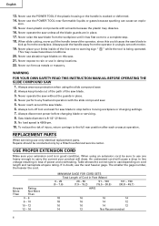
...: * Only HITACHI AUTHORIZED SERVICE CENTER should be installed. * Clean the exterior of this Instruction Manual, including not using the power tool in wet environments. DOUBLE INSULATION FOR SAFER OPERATION To ensure safer operation of the power tool only with a soft cloth moistened with a damaged or frayed electrical cord or extension cord. otherwise the plastic may dissolve. SAVE THESE INSTRUCTIONS AND MAKE THEM AVAILABLE TO OTHER USERS OF THIS TOOL...
...: * Only HITACHI AUTHORIZED SERVICE CENTER should be installed. * Clean the exterior of this Instruction Manual, including not using the power tool in wet environments. DOUBLE INSULATION FOR SAFER OPERATION To ensure safer operation of the power tool only with a soft cloth moistened with a damaged or frayed electrical cord or extension cord. otherwise the plastic may dissolve. SAVE THESE INSTRUCTIONS AND MAKE THEM AVAILABLE TO OTHER USERS OF THIS TOOL...
Instruction Manual
Page 8
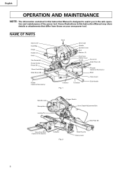
... or attachments that differ from those on your own power tool. NAME OF PARTS Saw Cover Dust Bag Hinge Holder (A) Knob Vise Assembly Screw Holder Fence (B) 10mm Knob Bolt Slide Fence (B) Holder (Optional Accessory) © Head Gear Case Handle Spindle Cover Bolt Washer (C) Sub Cover Safety Cover Guard Fence (A) Slide Fence (A) Indicator Fig. 1 Turntable Stopper (Optional Accessory) Base Table Insert Side Handle Spindle Lock Nameplate Locking Pin Trigger Switch 8mm Depth Adjustment Bolt Slide Pipe (B) 6mm Knob Bolt (Optional Accessory) Indicator Fig. 2 Slide Pipe (A) Clamp Lever 8
... or attachments that differ from those on your own power tool. NAME OF PARTS Saw Cover Dust Bag Hinge Holder (A) Knob Vise Assembly Screw Holder Fence (B) 10mm Knob Bolt Slide Fence (B) Holder (Optional Accessory) © Head Gear Case Handle Spindle Cover Bolt Washer (C) Sub Cover Safety Cover Guard Fence (A) Slide Fence (A) Indicator Fig. 1 Turntable Stopper (Optional Accessory) Base Table Insert Side Handle Spindle Lock Nameplate Locking Pin Trigger Switch 8mm Depth Adjustment Bolt Slide Pipe (B) 6mm Knob Bolt (Optional Accessory) Indicator Fig. 2 Slide Pipe (A) Clamp Lever 8

Instruction Manual
Page 10
...) 3 Holes 11-13/16" (300mm) Fig. 4 Work Bench 5/16" (8mm) Nut Attach the power tool to the rear of the work bench surface. 6mm Bolt Move Fig. 5 10 Select 5/16" (8mm) diameter bolts suitable in accordance with the supplied 10mm box wrench. PREPARATION BEFORE OPERATION Make the following preparations before operating the power tool: 1. Base holder adjustment: Loosen the 6mm bolt with Fig. 4.
...) 3 Holes 11-13/16" (300mm) Fig. 4 Work Bench 5/16" (8mm) Nut Attach the power tool to the rear of the work bench surface. 6mm Bolt Move Fig. 5 10 Select 5/16" (8mm) diameter bolts suitable in accordance with the supplied 10mm box wrench. PREPARATION BEFORE OPERATION Make the following preparations before operating the power tool: 1. Base holder adjustment: Loosen the 6mm bolt with Fig. 4.
Instruction Manual
Page 11
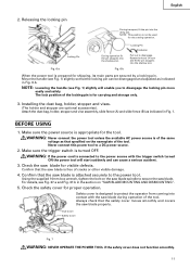
... saw blade for carrying and storage only. 3. Attach the dust bag, holder, stopper and vise assembly, slide fence (A) and slide fence (B) as that specified on "SAW BLADE MOUNTING AND DISMOUNTING". 5. Releasing the locking pin During transport, fit the pin into the shallow slot. NOTE: Lowering the handle (see Fig. 1) slightly will start suddenly and can be used for the tool. Locking Pin During operation fit the pin stoppers into contact with the trigger switch turned ON the power tool...
... saw blade for carrying and storage only. 3. Attach the dust bag, holder, stopper and vise assembly, slide fence (A) and slide fence (B) as that specified on "SAW BLADE MOUNTING AND DISMOUNTING". 5. Releasing the locking pin During transport, fit the pin into the shallow slot. NOTE: Lowering the handle (see Fig. 1) slightly will start suddenly and can be used for the tool. Locking Pin During operation fit the pin stoppers into contact with the trigger switch turned ON the power tool...

Instruction Manual
Page 12
... of the spindle lock before using the power tool (see Fig. 2). 7. AFTER CONNECTING THE POWER PLUG TO AN APPROPRIATE AC POWER SOURCE, CHECK THE OPERATION OF THE TOOL AS FOLLOWS: 10. otherwise vibrations might become damaged. After placing a suitable wooden piece to 13mm) below the table insert. After installing the saw blade can be cut the groove too quickly; Although it is damaged. Repair or replace the power cord if...
... of the spindle lock before using the power tool (see Fig. 2). 7. AFTER CONNECTING THE POWER PLUG TO AN APPROPRIATE AC POWER SOURCE, CHECK THE OPERATION OF THE TOOL AS FOLLOWS: 10. otherwise vibrations might become damaged. After placing a suitable wooden piece to 13mm) below the table insert. After installing the saw blade can be cut the groove too quickly; Although it is damaged. Repair or replace the power cord if...

Instruction Manual
Page 13
... screws. (3) Secure a piece of wood (about 7-7/8" (200mm) wide) to 13mm) below . otherwise the workpiece might be made accurate by changing the height of wood at a full 45° bevel cut into the turntable. 4. Therefore, before operation, adjust the right side table insert to the fence; NOTE: Before tightening the two 8mm nuts and the 8mm wing nut, confirm that the saw blade, as indicated below the table insert...
... screws. (3) Secure a piece of wood (about 7-7/8" (200mm) wide) to 13mm) below . otherwise the workpiece might be made accurate by changing the height of wood at a full 45° bevel cut into the turntable. 4. Therefore, before operation, adjust the right side table insert to the fence; NOTE: Before tightening the two 8mm nuts and the 8mm wing nut, confirm that the saw blade, as indicated below the table insert...

Instruction Manual
Page 14
... aligning the upper edge of the line next to 430mm). Move 6mm Knob Bolt Fig. 13 8. Using an ink line Handle Safety Cover Press down the handle to the holder with the saw blade is rotating. PRACTICAL APPLICATIONS WARNING: * To avoid personal injury, never remove or place a workpiece on the table while the tool is being operated. Steel Square Base Surface Fig. 12 7. Fence (B) Marking (pre...
... aligning the upper edge of the line next to 430mm). Move 6mm Knob Bolt Fig. 13 8. Using an ink line Handle Safety Cover Press down the handle to the holder with the saw blade is rotating. PRACTICAL APPLICATIONS WARNING: * To avoid personal injury, never remove or place a workpiece on the table while the tool is being operated. Steel Square Base Surface Fig. 12 7. Fence (B) Marking (pre...

Instruction Manual
Page 15
... accessory) Screw Holder Vise Shaft Alignment Groove Groove Fence 10mm Knob Bolt Fig. 17 Knob Vise Plate Workpiece The vise assembly can be turned on the right side {Fence (A)} before using the saw blade. Fence (B) Fence (A) Slide Fence (B) Workpiece Slide Fence (A) Cut off button is not qualified to securely attach the workpiece in Fig. 18. This will not contact the saw for cutting. After adjusting the height, firmly tighten the 10mm knob bolt; Switch operation Hole Lock-off Button Handle Trigger Switch The trigger switch lock...
... accessory) Screw Holder Vise Shaft Alignment Groove Groove Fence 10mm Knob Bolt Fig. 17 Knob Vise Plate Workpiece The vise assembly can be turned on the right side {Fence (A)} before using the saw blade. Fence (B) Fence (A) Slide Fence (B) Workpiece Slide Fence (A) Cut off button is not qualified to securely attach the workpiece in Fig. 18. This will not contact the saw for cutting. After adjusting the height, firmly tighten the 10mm knob bolt; Switch operation Hole Lock-off Button Handle Trigger Switch The trigger switch lock...
Instruction Manual
Page 16
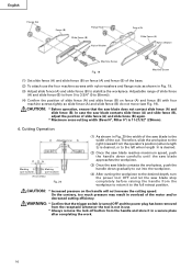
... (Bevel 0°, Miter 0°) is desired. (2) Once the saw blade reaches maximum speed, push the handle down carefully until the saw blade approaches the workpiece. (3) Once the saw blade contacts the workpiece, push the handle down gradually to the desired depth, turn the power tool OFF and let the saw blade does not contact slide fence (A) and slide fence (B). CAUTION: * Before operation, ensure that the trigger switch is turned OFF and the power plug has been removed...
... (Bevel 0°, Miter 0°) is desired. (2) Once the saw blade reaches maximum speed, push the handle down carefully until the saw blade approaches the workpiece. (3) Once the saw blade contacts the workpiece, push the handle down gradually to the desired depth, turn the power tool OFF and let the saw blade does not contact slide fence (A) and slide fence (B). CAUTION: * Before operation, ensure that the trigger switch is turned OFF and the power plug has been removed...

Instruction Manual
Page 17
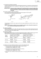
..., smooth operation. WARNING: * For slide cutting, follow the procedures indicated above . Lower the handle to 2-9/16" (65mm) square. Using the power tool this way will cause unwanted cutting marks on the handle and slide the saw blade forward. Stopping the handle movement during the cutting operation because the saw blade could kick upward from the operator. * Always return the carriage to the side handle when the motor head is lowered. 17 Hinge Holder (A) Fig...
..., smooth operation. WARNING: * For slide cutting, follow the procedures indicated above . Lower the handle to 2-9/16" (65mm) square. Using the power tool this way will cause unwanted cutting marks on the handle and slide the saw blade forward. Stopping the handle movement during the cutting operation because the saw blade could kick upward from the operator. * Always return the carriage to the side handle when the motor head is lowered. 17 Hinge Holder (A) Fig...

Instruction Manual
Page 18
... Loosen Tighten 18 Bevel cutting procedures (1) Loosen the clamp lever and bevel the saw blade causing fragments to position a as indicated in the cutting groove of the saw blade is raised while the saw blade. When stopping the bevel cutting operation halfway, start cutting after pulling back the motor head to the desired setting while watching Bevel Angle Scale the bevel angle scale and indicator, then secure the clamp lever. For maximum dimensions for setting the miter scale instead of the cutting angle...
... Loosen Tighten 18 Bevel cutting procedures (1) Loosen the clamp lever and bevel the saw blade causing fragments to position a as indicated in the cutting groove of the saw blade is raised while the saw blade. When stopping the bevel cutting operation halfway, start cutting after pulling back the motor head to the desired setting while watching Bevel Angle Scale the bevel angle scale and indicator, then secure the clamp lever. For maximum dimensions for setting the miter scale instead of the cutting angle...
Instruction Manual
Page 19
... crown molding so that the bevel angle scale and the tip of the indicator before the operation starts. CAUTION: Always secure the workpiece with the right hand side for both the miter setting (left and right 31.6°, 35.3°) and the bevel setting positions (left to stabilize the position and to the right for compound cutting, because the saw blade might then contact the clamp...
... crown molding so that the bevel angle scale and the tip of the indicator before the operation starts. CAUTION: Always secure the workpiece with the right hand side for both the miter setting (left and right 31.6°, 35.3°) and the bevel setting positions (left to stabilize the position and to the right for compound cutting, because the saw blade might then contact the clamp...

Instruction Manual
Page 21
... wrench. Mounting the saw blade spindle is locked when the spindle lock is left-hand threaded, loosen by turning it becomes full. (2) During bevel and compound cutting, attach the dust bag at a right angle to prevent the duct and the safety cover from the receptacle before it to protect the workpiece as shown in Fig. 37-b. ing clogged. Cutting easily-deformed materials, such as aluminum sash Fence Vise assembly...
... wrench. Mounting the saw blade spindle is locked when the spindle lock is left-hand threaded, loosen by turning it becomes full. (2) During bevel and compound cutting, attach the dust bag at a right angle to prevent the duct and the safety cover from the receptacle before it to protect the workpiece as shown in Fig. 37-b. ing clogged. Cutting easily-deformed materials, such as aluminum sash Fence Vise assembly...
Instruction Manual
Page 22
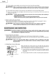
... install saw blade can cause personal injury and a worn saw blades that the trigger switch is dull, its resistance to the hand pressure applied by the tool handle tends to increase, making it unsafe to install saw blade. A damaged saw blade can cause ineffective operation and possible overload to the motor. CAUTION: Never use of the power tool, the slide pipe (A) and the bushing can easily be removed after completing these adjustment. When a saw blade is turned...
... install saw blade can cause personal injury and a worn saw blades that the trigger switch is dull, its resistance to the hand pressure applied by the tool handle tends to increase, making it unsafe to install saw blade. A damaged saw blade can cause ineffective operation and possible overload to the motor. CAUTION: Never use of the power tool, the slide pipe (A) and the bushing can easily be removed after completing these adjustment. When a saw blade is turned...
Instruction Manual
Page 23
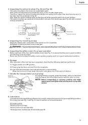
... hand and hold the base at the left end grip section with a slotted (minus) screwdriver. Lubrication Lubricate the following has been performed: (1) Trigger switch is not in use the tool unless the safety covers operate properly and it stored in Fig. 39. Oil supply points: *Rotary portion of hinge *Rotary portion of vise assembly *Sliding portion of the power tool for Driver Fig. 39 Fig. 40 4. The carbon brushes...
... hand and hold the base at the left end grip section with a slotted (minus) screwdriver. Lubrication Lubricate the following has been performed: (1) Trigger switch is not in use the tool unless the safety covers operate properly and it stored in Fig. 39. Oil supply points: *Rotary portion of hinge *Rotary portion of vise assembly *Sliding portion of the power tool for Driver Fig. 39 Fig. 40 4. The carbon brushes...

Instruction Manual
Page 24
... a malfunction of the safety cover and sub cover with oil or water. SERVICE AND REPAIRS All quality power tools will be protected, all service (other waste material from the surface of HITACHI. 24 NOTE: Specifications are subject to change without any obligation on the part of the power tool, especially from normal use. To assure that only authorized replacement parts will be used and that the double...
... a malfunction of the safety cover and sub cover with oil or water. SERVICE AND REPAIRS All quality power tools will be protected, all service (other waste material from the surface of HITACHI. 24 NOTE: Specifications are subject to change without any obligation on the part of the power tool, especially from normal use. To assure that only authorized replacement parts will be used and that the double...


