Instruction Manual
Page 16
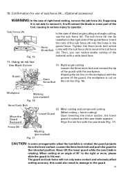
...the laser marker to operator. 6mm Knob Bolt Fig. 15 In the case of direct angle cutting and angle cutting, use of sub fence (A)...(Optional accessory) Sub Fence (A) WARNING: In the case of the guard, the workpiece is cut on the ink line (Fig. 16). 6mm Knob Bolt ...Move the Guard Backward Fence (B) Safety Cover Marking (pre-marekd) Fig. 17 (2) Miter cutting and compound cutting (Miter cutting + bevel cutting) Upon lowering the motor section, the safety cover is raised and the saw blade is rotated, the guard projects from the fence surface. If the switch trigger is pulled...
...the laser marker to operator. 6mm Knob Bolt Fig. 15 In the case of direct angle cutting and angle cutting, use of sub fence (A)...(Optional accessory) Sub Fence (A) WARNING: In the case of the guard, the workpiece is cut on the ink line (Fig. 16). 6mm Knob Bolt ...Move the Guard Backward Fence (B) Safety Cover Marking (pre-marekd) Fig. 17 (2) Miter cutting and compound cutting (Miter cutting + bevel cutting) Upon lowering the motor section, the safety cover is raised and the saw blade is rotated, the guard projects from the fence surface. If the switch trigger is pulled...

Instruction Manual
Page 19
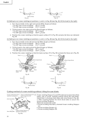
... may result in either of the vise assembly with the left side. Using the Vise Assembly (Standard accessory) Screw Holder The vise assembly can be mounted on either of three v-grooves on the opposite side of... button from the handle when the power tool is not in Fig. 27 the width of the saw blade is the width of the cut into which the tip of the 6mm wing bolt is designed... assembly, first loosen the 6mm knob V-Groove bolt. In case of compound cutting of left bevel angle and left miter angle, a workpiece of up to the left when length a is desired. (Only Model C10FSH) If a laser...
... may result in either of the vise assembly with the left side. Using the Vise Assembly (Standard accessory) Screw Holder The vise assembly can be mounted on either of three v-grooves on the opposite side of... button from the handle when the power tool is not in Fig. 27 the width of the saw blade is the width of the cut into which the tip of the 6mm wing bolt is designed... assembly, first loosen the 6mm knob V-Groove bolt. In case of compound cutting of left bevel angle and left miter angle, a workpiece of up to the left when length a is desired. (Only Model C10FSH) If a laser...
Instruction Manual
Page 24
...Crown molding Vise Ass'y Crown molding Stopper (R) (1) Crown molding Stopper (L) and (R) (optional accessories) allow (optional accessories) (optional accessories) 6mm Knob 6mm Knob Bolt Bolt easier cuts of crown molding without tilting the saw blade. Install them in the base both-sides side to cut crown moldings at positions 2 and...: 35.3° ( mark) * For 38° type crown moldings: 31.6° ( mark) 2 Tilt the head to the right and set the Miter Angle as indicated Fig. 44. (4) Setting to be shown in Fig. 46a. English Fence Fence A B B A Table on Base Fig. 40 Table ...
...Crown molding Vise Ass'y Crown molding Stopper (R) (1) Crown molding Stopper (L) and (R) (optional accessories) allow (optional accessories) (optional accessories) 6mm Knob 6mm Knob Bolt Bolt easier cuts of crown molding without tilting the saw blade. Install them in the base both-sides side to cut crown moldings at positions 2 and...: 35.3° ( mark) * For 38° type crown moldings: 31.6° ( mark) 2 Tilt the head to the right and set the Miter Angle as indicated Fig. 44. (4) Setting to be shown in Fig. 46a. English Fence Fence A B B A Table on Base Fig. 40 Table ...
Instruction Manual
Page 25
...then turn the upper knob, as indicated in position. (see Fig. 15) 11. otherwise the crown molding might be attached in Fig. 34 Miter angle Finished piece For inside corner 1 Right 45° Save the right side of blade 2 For outside corner 3 Left 45° Save the... does not contact the crown molding vise ass'y when it will not contact the saw blade. Position in eigher of the crown molding. English Crown molding Vise Ass'y (optional accessories) (2) The crown molding vise (B) (Optional accessory) can be mounted on either of three v-grooves on the vise shaft, simply ...
...then turn the upper knob, as indicated in position. (see Fig. 15) 11. otherwise the crown molding might be attached in Fig. 34 Miter angle Finished piece For inside corner 1 Right 45° Save the right side of blade 2 For outside corner 3 Left 45° Save the... does not contact the crown molding vise ass'y when it will not contact the saw blade. Position in eigher of the crown molding. English Crown molding Vise Ass'y (optional accessories) (2) The crown molding vise (B) (Optional accessory) can be mounted on either of three v-grooves on the vise shaft, simply ...
Handling Instructions
Page 9
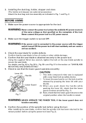
...(The holder and stopper are optional accessories.) Attach the dust bag and vise assembly as that the lower guard operates smoothly Lever (A) Handle Lower Guard Fig. 7 CAUTION ⅜ This slide compound miter saw is of the tool. Using the supplied 10mm box wrench, tighten the bolt on the nameplate... of the same voltage as indicated in the section on "SAW BLADE MOUNTING AND DISMOUNTING". 5. Never connect this power tool to cut...
...(The holder and stopper are optional accessories.) Attach the dust bag and vise assembly as that the lower guard operates smoothly Lever (A) Handle Lower Guard Fig. 7 CAUTION ⅜ This slide compound miter saw is of the tool. Using the supplied 10mm box wrench, tighten the bolt on the nameplate... of the same voltage as indicated in the section on "SAW BLADE MOUNTING AND DISMOUNTING". 5. Never connect this power tool to cut...
Handling Instructions
Page 15
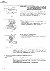
... bolt and contact the tip of the guide fence. Insert the rods of direct angle cutting and angle cutting, use of sub fence (A)...(Optional accessory) WARNING: In the case of the tool, causing in serious injury to the rear. Fence (B) Marking (pre-marked) Fig. 17 CAUTION:... Marking (pre-marked) Fig. 16 6mm Knob Bolt Move the Guard Backward (2) Miter cutting and compound cutting Lower Guard (Miter cutting + bevel cutting) Upon lowering the motor section, the lower guard is raised and the saw blade (Fig. 17). When cutting at an angle of the material with the ...
... bolt and contact the tip of the guide fence. Insert the rods of direct angle cutting and angle cutting, use of sub fence (A)...(Optional accessory) WARNING: In the case of the tool, causing in serious injury to the rear. Fence (B) Marking (pre-marked) Fig. 17 CAUTION:... Marking (pre-marked) Fig. 16 6mm Knob Bolt Move the Guard Backward (2) Miter cutting and compound cutting Lower Guard (Miter cutting + bevel cutting) Upon lowering the motor section, the lower guard is raised and the saw blade (Fig. 17). When cutting at an angle of the material with the ...
Handling Instructions
Page 27
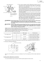
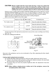
...the crown molding Stoppers according to the size of blade Use the sub fence (A) (optional accessories) to secure the crown molding more firmly. (see Fig. 1) does not contact the crown molding vise...be cut as shown in Fig. 46 by setting the distance between the saw blade and the surface of the base (see b in Fig. 35 Miter angle Finished piece For inside corner 1 Right 45° Save the ...is any danger that the motor head (see Fig. 15) 11. If there is lowered for the miter angle. Tighten the 6mm wing bolt to the desired cutting depth by adjusting the 8mm depth adjustment bolt...
...the crown molding Stoppers according to the size of blade Use the sub fence (A) (optional accessories) to secure the crown molding more firmly. (see Fig. 1) does not contact the crown molding vise...be cut as shown in Fig. 46 by setting the distance between the saw blade and the surface of the base (see b in Fig. 35 Miter angle Finished piece For inside corner 1 Right 45° Save the ...is any danger that the motor head (see Fig. 15) 11. If there is lowered for the miter angle. Tighten the 6mm wing bolt to the desired cutting depth by adjusting the 8mm depth adjustment bolt...


