

Instruction Manual
Page 3
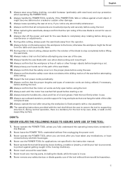
... safety procedures. Always remove the lock-off button from the work place tamper-proof by HITACHI. Never force a tool or an attachment to prevent bodily injury or machine damage are ...which , if ignored, could result in this electric tool, take all keys and adjusting wrenches have been removed from power tool operation and maintenance are identified by the failure to minimize...particular, always comply with steel toes. ALWAYS KEEP GUARDS IN PLACE and in the moving parts. Avoid injuries by recognizing a potentially hazardous situation before it is turned on the power...
... safety procedures. Always remove the lock-off button from the work place tamper-proof by HITACHI. Never force a tool or an attachment to prevent bodily injury or machine damage are ...which , if ignored, could result in this electric tool, take all keys and adjusting wrenches have been removed from power tool operation and maintenance are identified by the failure to minimize...particular, always comply with steel toes. ALWAYS KEEP GUARDS IN PLACE and in the moving parts. Avoid injuries by recognizing a potentially hazardous situation before it is turned on the power...

Instruction Manual
Page 4
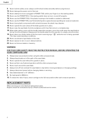
...Always follow instructions for lubricating the tool and for the best and safest performance. ALWAYS CHECK FOR DAMAGED PARTS BEFORE USING THE TOOL. Always check the guard and all moving parts for proper alignment, freedom from the workpiece until it comes to reduce the risk of the blade in...wider than using the tool. 18. Also, use a face mask for Use of recommended accessories.To avoid personal injuries, use only authorized replacement parts. 22. ALWAYS MAINTAIN TOOLS WITH CARE. NEVER STAND ON THE TOOL. Prevent serious injury by not tipping the tool and by not risking ...
...Always follow instructions for lubricating the tool and for the best and safest performance. ALWAYS CHECK FOR DAMAGED PARTS BEFORE USING THE TOOL. Always check the guard and all moving parts for proper alignment, freedom from the workpiece until it comes to reduce the risk of the blade in...wider than using the tool. 18. Also, use a face mask for Use of recommended accessories.To avoid personal injuries, use only authorized replacement parts. 22. ALWAYS MAINTAIN TOOLS WITH CARE. NEVER STAND ON THE TOOL. Prevent serious injury by not tipping the tool and by not risking ...
Instruction Manual
Page 5
... operator. 10. Never leave the POWER TOOL unattended without them would be thrust form the table and cause bodily harm. 11. Never remove any moving parts, including the blade, while the saw . 24. Always confirm that the proper lengths and types of the slide compound saw is a tendency for the saw...
... operator. 10. Never leave the POWER TOOL unattended without them would be thrust form the table and cause bodily harm. 11. Never remove any moving parts, including the blade, while the saw . 24. Always confirm that the proper lengths and types of the slide compound saw is a tendency for the saw...
Instruction Manual
Page 6
... servicing use the POWER TOOL near flammable liquids or gases because sparking can cause an explosion. 15. Repairs should be conducted only by a Hitachi authorized service center. 6 always confirm that it has first come to warning sign " " while the tool is 3800/min. 10. Never attempt ...to stop . 18. Never use the POWER TOOL if the plastic housing or the handle is 10" (255mm). 9. Never use only identical replacement parts. Never perform any freehand operation with solvents because the plastic may cause hazardous conditions. 20. Saw blade diameter is cracked or deformed. 14. No...
... servicing use the POWER TOOL near flammable liquids or gases because sparking can cause an explosion. 15. Repairs should be conducted only by a Hitachi authorized service center. 6 always confirm that it has first come to warning sign " " while the tool is 3800/min. 10. Never attempt ...to stop . 18. Never use the POWER TOOL if the plastic housing or the handle is 10" (255mm). 9. Never use only identical replacement parts. Never perform any freehand operation with solvents because the plastic may cause hazardous conditions. 20. Saw blade diameter is cracked or deformed. 14. No...
Instruction Manual
Page 7
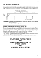
...environments. Never use the next heavier gage. Although this system has no external grounding, you must still follow these precautions: * Only HITACHI AUTHORIZED SERVICE CENTER should disassemble or assemble this tool with soapy water and dry thoroughly. * Never use one heavy enough to the ...12 Not Recommended WARNING: Avoid electrical shock hazard. Table shows the correct size to use this power tool, and only genuine HITACHI replacement parts should be sure to use solvents, gasoline or thinners on the nameplate. DOUBLE INSULATION FOR SAFER OPERATION To ensure safer operation ...
...environments. Never use the next heavier gage. Although this system has no external grounding, you must still follow these precautions: * Only HITACHI AUTHORIZED SERVICE CENTER should disassemble or assemble this tool with soapy water and dry thoroughly. * Never use one heavy enough to the ...12 Not Recommended WARNING: Avoid electrical shock hazard. Table shows the correct size to use this power tool, and only genuine HITACHI replacement parts should be sure to use solvents, gasoline or thinners on the nameplate. DOUBLE INSULATION FOR SAFER OPERATION To ensure safer operation ...

Instruction Manual
Page 8
NAME OF PARTS MODEL C10FSH/MODEL C10FSB Dust Bag Hinge Gear Case Motor Head Moter Handle Spindle Cover Holder (A) Saw Blade Indicator (For right bevel scale) Leser Marker (...
NAME OF PARTS MODEL C10FSH/MODEL C10FSB Dust Bag Hinge Gear Case Motor Head Moter Handle Spindle Cover Holder (A) Saw Blade Indicator (For right bevel scale) Leser Marker (...

Instruction Manual
Page 11
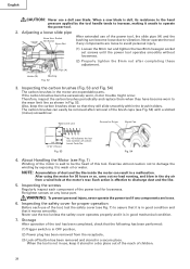
... holder until its bottom surface contacts the work bench surface. Releasing the locking pin Handle When the power tool is for shipping, its main parts are optional accessories.) Attach the dust bag and vise assembly as indicated in Fig. 1 and Fig. 2. 11 NOTE: Lowering the handle...to disengage the locking pin more easily and safely. Move Fig. 5 2. Select 5/16" (8mm) diameter bolts suitable in accordance with the supplied 10mm box wrench. After adjustment, firmly tighten the 6mm bolt. Locking Pin Pull Fig. 6 3. Installing the dust bag, holder, stopper and vises (The holder and ...
... holder until its bottom surface contacts the work bench surface. Releasing the locking pin Handle When the power tool is for shipping, its main parts are optional accessories.) Attach the dust bag and vise assembly as indicated in Fig. 1 and Fig. 2. 11 NOTE: Lowering the handle...to disengage the locking pin more easily and safely. Move Fig. 5 2. Select 5/16" (8mm) diameter bolts suitable in accordance with the supplied 10mm box wrench. After adjustment, firmly tighten the 6mm bolt. Locking Pin Pull Fig. 6 3. Installing the dust bag, holder, stopper and vises (The holder and ...
Instruction Manual
Page 16
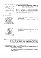
..., you can be used for use the sub fence (A). When cutting at an angle of right bevel cutting, remove the sub fence (A). CAUTION: In some part of the guard with the sub fence (A) to the rear. Loosen the 6mm knob bolt and push the guard to the guard. 12. The guard...
..., you can be used for use the sub fence (A). When cutting at an angle of right bevel cutting, remove the sub fence (A). CAUTION: In some part of the guard with the sub fence (A) to the rear. Loosen the 6mm knob bolt and push the guard to the guard. 12. The guard...
Instruction Manual
Page 28
... become worn to vibration. Wear Limit Line Groove for 50 hours or so, carry out no-load running, and blow in the motor are expendable parts. After using the motor for Driver Brush Cap 43 1/4" (6mm) 11/16" (17mm) Fig. 53 No. 43 indicates the last two numbers of the tool... caps (see Fig. 7) to assure that it to operate the power tool. 2. WARNING: To prevent personal injury, never operate the power tool if any loose part. Exercise utmost caution not to damage the winding by the tool handle tends to increase, making it unsafe to wash oil or water. Re-tighten...
... become worn to vibration. Wear Limit Line Groove for 50 hours or so, carry out no-load running, and blow in the motor are expendable parts. After using the motor for Driver Brush Cap 43 1/4" (6mm) 11/16" (17mm) Fig. 53 No. 43 indicates the last two numbers of the tool... caps (see Fig. 7) to assure that it to operate the power tool. 2. WARNING: To prevent personal injury, never operate the power tool if any loose part. Exercise utmost caution not to damage the winding by the tool handle tends to increase, making it unsafe to wash oil or water. Re-tighten...

Instruction Manual
Page 29
... protect it . Refer to keep the power tool in the guard may widen and require replacement. Cutting a groove on the guard" on the part of guard (C) Guard After long-term use . Fig. 55 9. Replacement of Poly-V-Belt Poly-V-Belt Pulley (A) The power of the laser marker...Lubrication Lubricate the following sliding surfaces once a month to "1. NOTE: Specifications are subject to the saw blade by an AUTHORIZED HITACHI POWER TOOL REPAIR CENTER ONLY. Replacement of HITACHI. 29 If the blade slot should widen, replace the guard with a damp, soapy cloth. When the Poly-V-Belt is...
... protect it . Refer to keep the power tool in the guard may widen and require replacement. Cutting a groove on the guard" on the part of guard (C) Guard After long-term use . Fig. 55 9. Replacement of Poly-V-Belt Poly-V-Belt Pulley (A) The power of the laser marker...Lubrication Lubricate the following sliding surfaces once a month to "1. NOTE: Specifications are subject to the saw blade by an AUTHORIZED HITACHI POWER TOOL REPAIR CENTER ONLY. Replacement of HITACHI. 29 If the blade slot should widen, replace the guard with a damp, soapy cloth. When the Poly-V-Belt is...

Parts List
Page 1
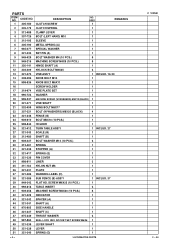
Hitachi Power Tools LIST NO. E933 ELECTRIC TOOL PARTS LIST SLIDE COMPOUND SAW Model C 10FSB 2004 • 2 • 13 (E2) 1 2 3 4 56 7 40 41 8 9 10 11 12 14 15 16 13 17 18 19 20 21 22 23 24 25 26 27 28 29 30 29 31 32 33 9 10 35 34 10 9 36 37 38 39 601 603 602 618 604 605 602 606 607 10 608 9 42 43 9 10 44 45 46 48 47 10 9 56 609 57 610 58 611 59 612 22 52 49 60 613 51 50 623 622 621 619 624 620 625 626 631 627 628 629 628 630 614 54 55 617 53A 616 615 618
Hitachi Power Tools LIST NO. E933 ELECTRIC TOOL PARTS LIST SLIDE COMPOUND SAW Model C 10FSB 2004 • 2 • 13 (E2) 1 2 3 4 56 7 40 41 8 9 10 11 12 14 15 16 13 17 18 19 20 21 22 23 24 25 26 27 28 29 30 29 31 32 33 9 10 35 34 10 9 36 37 38 39 601 603 602 618 604 605 602 606 607 10 608 9 42 43 9 10 44 45 46 48 47 10 9 56 609 57 610 58 611 59 612 22 52 49 60 613 51 50 623 622 621 619 624 620 625 626 631 627 628 629 628 630 614 54 55 617 53A 616 615 618
Parts List
Page 4
... 2 48 987-860 SEAL LOCK HEX. SOCKET SET SCREW M6X6 1 49 321-339 LEVER SHAFT 1 50 321-338 LEVER 1 51 321-340 SPRING (D) 1 --- 4 --- * ALTERNATIVE PARTS C 10FSB 2 -- 04 PARTS ITEM NO. USED 1 REMARKS 2 305-179 CLUTCH SPRING 1 3 312-488 CLAMP LEVER 1 4 307-725 BOLT (LEFT HAND) M10 1 5 315-195 SLEEVE 1 6 305-190 METAL...
... 2 48 987-860 SEAL LOCK HEX. SOCKET SET SCREW M6X6 1 49 321-339 LEVER SHAFT 1 50 321-338 LEVER 1 51 321-340 SPRING (D) 1 --- 4 --- * ALTERNATIVE PARTS C 10FSB 2 -- 04 PARTS ITEM NO. USED 1 REMARKS 2 305-179 CLUTCH SPRING 1 3 312-488 CLAMP LEVER 1 4 307-725 BOLT (LEFT HAND) M10 1 5 315-195 SLEEVE 1 6 305-190 METAL...
Parts List
Page 5
....) 2 94 974-500 HEX. SOCKET SET SCREW M6X10 2 * 104 302-503 KNOB BOLT M6X22 1 FOR USA, CAN, AUS, NZL 105 321-333 GUARD (A) 1 2 -- 04 * ALTERNATIVE PARTS --- 5 --- PARTS ITEM NO. SOCKET SET SCREW M8X16 2 95 302-459 WING BOLT M6X17 1 96 947-859 LOCK SPRING 1 97 963-174 CLAMP PIECE (B) 1 98 320-206...
....) 2 94 974-500 HEX. SOCKET SET SCREW M6X10 2 * 104 302-503 KNOB BOLT M6X22 1 FOR USA, CAN, AUS, NZL 105 321-333 GUARD (A) 1 2 -- 04 * ALTERNATIVE PARTS --- 5 --- PARTS ITEM NO. SOCKET SET SCREW M8X16 2 95 302-459 WING BOLT M6X17 1 96 947-859 LOCK SPRING 1 97 963-174 CLAMP PIECE (B) 1 98 320-206...

Parts List
Page 6
... (A) ASS'Y BRUSH TERMINAL 1 1 FOR USA, CAN 4 3 FOR USA, CAN 1 INCLUD. 134, 146 1 INCLUD. 134, 146 FOR USA, CAN 2 INCLUD. 134, 146 FOR USA, CAN --- 6 --- * ALTERNATIVE PARTS C 10FSB 2 -- 04 USED 1 REMARKS * 107 * 107 * 107 500-234Z 500-241Z 500-435Z CORD CORD CORD 1 1 FOR USA, CAN 1 FOR GBR (230V) * 107 500-463Z... 960-092 WAVE WASHER 1 FOR USA, CAN 109 * 110 * 111 * 112 * 113 322-210 949-332 322-206 311-144 948-363 LINER (A) FLAT HD. PARTS ITEM NO. CODE NO. 106 321-394 DESCRIPTION GUARD HOLDER NO.
... (A) ASS'Y BRUSH TERMINAL 1 1 FOR USA, CAN 4 3 FOR USA, CAN 1 INCLUD. 134, 146 1 INCLUD. 134, 146 FOR USA, CAN 2 INCLUD. 134, 146 FOR USA, CAN --- 6 --- * ALTERNATIVE PARTS C 10FSB 2 -- 04 USED 1 REMARKS * 107 * 107 * 107 500-234Z 500-241Z 500-435Z CORD CORD CORD 1 1 FOR USA, CAN 1 FOR GBR (230V) * 107 500-463Z... 960-092 WAVE WASHER 1 FOR USA, CAN 109 * 110 * 111 * 112 * 113 322-210 949-332 322-206 311-144 948-363 LINER (A) FLAT HD. PARTS ITEM NO. CODE NO. 106 321-394 DESCRIPTION GUARD HOLDER NO.
Parts List
Page 7
... 1 184 308-788 BEARING HOLDER 1 185 608-VVM BALL BEARING 608VVC2PS2L 2 186 PINION 1 187 931-008 FEATHER KEY 4X4X12 1 2 -- 04 * ALTERNATIVE PARTS C 10FSB --- 7 --- HD. PARTS ITEM NO. SOCKET SET SCREW M5X8 2 * 158 322-208 HOUSING ASS'Y 1 INCLUD. 156, 157 * 158 321-379 HOUSING ASS'Y 1 INCLUD. 156,... PCS.) 1 164 606-ZZM BALL BEARING 606ZZC2PS2L 1 165 949-455 SPRING WASHER M6 (10 PCS.) 1 166 949-425 WASHER M6 (10 PCS.) 1 167 HITACHI LABEL 1 168 WARNING LABEL (G) 1 FOR USA, CAN 169 304-043 MACHINE SCREW (W/WASHERS) M4X10 (BLACK) 1 170 877-839 SEAL LOCK HEX. BOLT M5X10...
... 1 184 308-788 BEARING HOLDER 1 185 608-VVM BALL BEARING 608VVC2PS2L 2 186 PINION 1 187 931-008 FEATHER KEY 4X4X12 1 2 -- 04 * ALTERNATIVE PARTS C 10FSB --- 7 --- HD. PARTS ITEM NO. SOCKET SET SCREW M5X8 2 * 158 322-208 HOUSING ASS'Y 1 INCLUD. 156, 157 * 158 321-379 HOUSING ASS'Y 1 INCLUD. 156,... PCS.) 1 164 606-ZZM BALL BEARING 606ZZC2PS2L 1 165 949-455 SPRING WASHER M6 (10 PCS.) 1 166 949-425 WASHER M6 (10 PCS.) 1 167 HITACHI LABEL 1 168 WARNING LABEL (G) 1 FOR USA, CAN 169 304-043 MACHINE SCREW (W/WASHERS) M4X10 (BLACK) 1 170 877-839 SEAL LOCK HEX. BOLT M5X10...
Parts List
Page 8
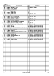
PARTS ITEM NO. USED REMARKS * 188 949-555 NUT M5 (10 PCS.) 1 EXCEPT FOR NZL 189 988-821 LOCK SPRING 1 190 307-732 STOPPER PIN 1 191 ...-043 MACHINE SCREW (W/WASHERS) M4X10 (BLACK) 1 EXCEPT FOR USA, CAN, AUS, NZL * 210 322-623 SUB COVER (A) 1 EXCEPT FOR USA, CAN, AUS, NZL C 10FSB --- 8 --- * ALTERNATIVE PARTS 2 -- 04 DESCRIPTION NO. CODE NO.
PARTS ITEM NO. USED REMARKS * 188 949-555 NUT M5 (10 PCS.) 1 EXCEPT FOR NZL 189 988-821 LOCK SPRING 1 190 307-732 STOPPER PIN 1 191 ...-043 MACHINE SCREW (W/WASHERS) M4X10 (BLACK) 1 EXCEPT FOR USA, CAN, AUS, NZL * 210 322-623 SUB COVER (A) 1 EXCEPT FOR USA, CAN, AUS, NZL C 10FSB --- 8 --- * ALTERNATIVE PARTS 2 -- 04 DESCRIPTION NO. CODE NO.
Parts List
Page 9
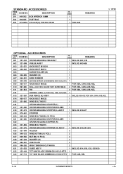
... * 632 322-444 TCT SAW BLADE 255MM-D30 HOLE-NT72 1 * 632 307-713 TCT SAW BLADE 255MM-D25.4 HOLE-NT72 1 FOR AUS, NZL 2 -- 04 * ALTERNATIVE PARTS --- 9 --- DESCRIPTION NO. USED REMARKS 601 321-434 CROWN MOLDING VISE ASS'Y 1 INCLUD. 602, 618 602 321-388 VISE (B) ASS'Y 1 INCLUD. 603-608 603 321-551... SCREW (W/WASHERS) M4X10 (BLACK) 1 * 609 960-017 KNOB BOLT M6X32 1 FOR USA, CAN, AUS, NZL * 610 987-860 SEAL LOCK HEX. DESCRIPTION 501 940-543 BOX WRENCH 10MM 502 998-845 DUST BAG * 503 974-663Z COLLAR (A) FOR D30 HOLE NO. CODE NO.
... * 632 322-444 TCT SAW BLADE 255MM-D30 HOLE-NT72 1 * 632 307-713 TCT SAW BLADE 255MM-D25.4 HOLE-NT72 1 FOR AUS, NZL 2 -- 04 * ALTERNATIVE PARTS --- 9 --- DESCRIPTION NO. USED REMARKS 601 321-434 CROWN MOLDING VISE ASS'Y 1 INCLUD. 602, 618 602 321-388 VISE (B) ASS'Y 1 INCLUD. 603-608 603 321-551... SCREW (W/WASHERS) M4X10 (BLACK) 1 * 609 960-017 KNOB BOLT M6X32 1 FOR USA, CAN, AUS, NZL * 610 987-860 SEAL LOCK HEX. DESCRIPTION 501 940-543 BOX WRENCH 10MM 502 998-845 DUST BAG * 503 974-663Z COLLAR (A) FOR D30 HOLE NO. CODE NO.

Handling Instructions
Page 2
... dust mask if cutting operations create dust. 10. Secure work area clean. Maintain tools with earthed or grounded surfaces. Do not use tools in moving parts. pipes, radiators, refrigerator enclosures. 4. Connect dust extraction equipment. Keep handles dry, clean and free from heat, oil and sharp edges. 12. GENERAL OPERATIONAL PRECAUTIONS WARNING...
... dust mask if cutting operations create dust. 10. Secure work area clean. Maintain tools with earthed or grounded surfaces. Do not use tools in moving parts. pipes, radiators, refrigerator enclosures. 4. Connect dust extraction equipment. Keep handles dry, clean and free from heat, oil and sharp edges. 12. GENERAL OPERATIONAL PRECAUTIONS WARNING...

Handling Instructions
Page 3
...in the handling instructions. 22. Never cut ferrous metals or masonry. 3 When not in . 18. Remove adjusting keys and wrenches. Stay alert. Check damaged parts. To ensure the designed operational integrity of personal injury. 23. Do not wipe them with soapy water. 29. Ensure switch ... accessories unless the power source has been disconnected. 27. otherwise, the finish may damage and crack plastic parts. Use only original HITACHI replacement parts. 30. This tool should only be done only by an authorized service center unless otherwise indicated in tool with ...
...in the handling instructions. 22. Never cut ferrous metals or masonry. 3 When not in . 18. Remove adjusting keys and wrenches. Stay alert. Check damaged parts. To ensure the designed operational integrity of personal injury. 23. Do not wipe them with soapy water. 29. Ensure switch ... accessories unless the power source has been disconnected. 27. otherwise, the finish may damage and crack plastic parts. Use only original HITACHI replacement parts. 30. This tool should only be done only by an authorized service center unless otherwise indicated in tool with ...

Handling Instructions
Page 5
NAME OF PARTS Dust Bag Hinge Holder (A) Sub Cover Indicator (For right bevel scale) Laser Marker (Only C10FSH) Saw Blade Motor Lever (A) Gear Case Head Handle Motor Spindle ...
NAME OF PARTS Dust Bag Hinge Holder (A) Sub Cover Indicator (For right bevel scale) Laser Marker (Only C10FSH) Saw Blade Motor Lever (A) Gear Case Head Handle Motor Spindle ...


