Instruction Manual
Page 3
.... PRODUCT SPECIFICATIONS MOTOR Power Source 120 V, AC, 60 Hz, 5.5 AMPS Belt Speed 1850 FPM (Feet Per Minute) Disc speed 3000 RPM Horsepower 1/3 HP (Continuous Duty) TABLE Size 6 x 9″ Tilt 0 - 45° DUST COLLECTION Yes BELT AND DISC Belt size 4″ x 36″ Disc size 8″ dia. Connect to the tool, use a 15 Amp time delay fuse or circuit breaker. To avoid shock or fire, replace power cord immediately if it is worn, cut or...
.... PRODUCT SPECIFICATIONS MOTOR Power Source 120 V, AC, 60 Hz, 5.5 AMPS Belt Speed 1850 FPM (Feet Per Minute) Disc speed 3000 RPM Horsepower 1/3 HP (Continuous Duty) TABLE Size 6 x 9″ Tilt 0 - 45° DUST COLLECTION Yes BELT AND DISC Belt size 4″ x 36″ Disc size 8″ dia. Connect to the tool, use a 15 Amp time delay fuse or circuit breaker. To avoid shock or fire, replace power cord immediately if it is worn, cut or...
Instruction Manual
Page 4
... rating. Sanding operation produces dust. 14. Dust generated from work area. 7. REMOVE ADJUSTING KEYS AND WRENCHES. Cluttered areas and benches invite accidents. 5. TURN POWER "OFF". check for lubricating and changing accessories. 23. DON'T USE IN DANGEROUS ENVIRONMENT. Wear protective hair covering to use of any other part that could cause permanent eye damage. NEVER LEAVE TOOL RUNNING UNATTENDED. ALWAYS WEAR EYE PROTECTION. English SAFETY GENERAL SAFETY INSTRUCTIONS BEFORE USING THE SANDER Safety is recommended...
... rating. Sanding operation produces dust. 14. Dust generated from work area. 7. REMOVE ADJUSTING KEYS AND WRENCHES. Cluttered areas and benches invite accidents. 5. TURN POWER "OFF". check for lubricating and changing accessories. 23. DON'T USE IN DANGEROUS ENVIRONMENT. Wear protective hair covering to use of any other part that could cause permanent eye damage. NEVER LEAVE TOOL RUNNING UNATTENDED. ALWAYS WEAR EYE PROTECTION. English SAFETY GENERAL SAFETY INSTRUCTIONS BEFORE USING THE SANDER Safety is recommended...
Instruction Manual
Page 5
... disc. 5. Do not force the work stop when sanding with belt and with table when sanding with a qualified electrician or service person if you do not stall motor or reduce speed. If repair or replacement of electric shock. AVOID kickback by sanding in accordance with or without yellow stripes) is properly installed and grounded in use to the tool, use a 15 Amp time delay fuse or circuit breaker. WITH power...
... disc. 5. Do not force the work stop when sanding with belt and with table when sanding with a qualified electrician or service person if you do not stall motor or reduce speed. If repair or replacement of electric shock. AVOID kickback by sanding in accordance with or without yellow stripes) is properly installed and grounded in use to the tool, use a 15 Amp time delay fuse or circuit breaker. WITH power...
Instruction Manual
Page 6
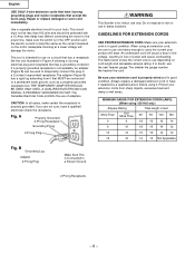
... the motor nameplate. If in good condition. Repair or replace damaged or worn cord immediately. When using an extension cord, be connected to a Known Ground WARNING This Sander is properly grounded. Protect your extension cord is in doubt, use only. MINIMUM GAUGE FOR EXTENSION CORDS (AWG) (When using it that MUST be sure to use one illustrated in good condition. The smaller the gauge number...
... the motor nameplate. If in good condition. Repair or replace damaged or worn cord immediately. When using an extension cord, be connected to a Known Ground WARNING This Sander is properly grounded. Protect your extension cord is in doubt, use only. MINIMUM GAUGE FOR EXTENSION CORDS (AWG) (When using it that MUST be sure to use one illustrated in good condition. The smaller the gauge number...
Instruction Manual
Page 7
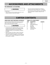
... from unexpected starting, do not plug the band sander in until the missing or damaged part is replaced, and assembly is complete. TABLE OF LOOSE PARTS ITEM A. D. F. DESCRIPTION Sander Table assembly Miter gauge assembly Dust bag Bag clamp Abrasive disc Long hex wrench Hex wrench QUANTITY 1 1 1 1 1 1 1 1 -7- E. G. Place the sander on a secure surface and examine it carefully. English ACCESSORIES AND ATTACHMENTS RECOMMENDED ACCESSORIES WARNING To avoid injury: • Follow instructions that accessory. To avoid...
... from unexpected starting, do not plug the band sander in until the missing or damaged part is replaced, and assembly is complete. TABLE OF LOOSE PARTS ITEM A. D. F. DESCRIPTION Sander Table assembly Miter gauge assembly Dust bag Bag clamp Abrasive disc Long hex wrench Hex wrench QUANTITY 1 1 1 1 1 1 1 1 -7- E. G. Place the sander on a secure surface and examine it carefully. English ACCESSORIES AND ATTACHMENTS RECOMMENDED ACCESSORIES WARNING To avoid injury: • Follow instructions that accessory. To avoid...
Instruction Manual
Page 9
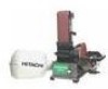
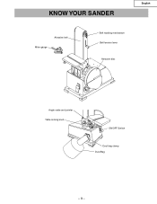
English KNOW YOUR SANDER Abrasive belt Miter gauge Belt tracking mechanism Belt tension lever Abrasive disc Angle scale and pointer Table locking knob ON/OFF Switch Dust bag clamp Dust Bag -9-
English KNOW YOUR SANDER Abrasive belt Miter gauge Belt tracking mechanism Belt tension lever Abrasive disc Angle scale and pointer Table locking knob ON/OFF Switch Dust bag clamp Dust Bag -9-
Instruction Manual
Page 10
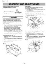
... tool. Secure with the disc: (Fig. Position table assembly (4) on rod. Secure with bolt (5) 3. Secure with bolt (5). 3. Choose a suitable location to the belt and secure in position with knob (6). Make sure there is used with knob (7). ATTACH ABRASIVE DISC. (Fig. Insert support rod (1) into base (2). C 1 2 7 4 3 3 5 1 6 2 - 10 - English ASSEMBLY AND ADJUSTMENTS ESTIMATED ASSEMBLY TIME 35-50 MINUTES ASSEMBLY INSTRUCTIONS Phillips Screwdriver Combination Square WARNING For your safety, never connect plug to power...
... tool. Secure with the disc: (Fig. Position table assembly (4) on rod. Secure with bolt (5) 3. Secure with bolt (5). 3. Choose a suitable location to the belt and secure in position with knob (6). Make sure there is used with knob (7). ATTACH ABRASIVE DISC. (Fig. Insert support rod (1) into base (2). C 1 2 7 4 3 3 5 1 6 2 - 10 - English ASSEMBLY AND ADJUSTMENTS ESTIMATED ASSEMBLY TIME 35-50 MINUTES ASSEMBLY INSTRUCTIONS Phillips Screwdriver Combination Square WARNING For your safety, never connect plug to power...

Instruction Manual
Page 11
... use . Remove the yellow switch key, when the sander has come to increase the clamp size. Remove the key and keep it in use . Place clamp (1) over the dust port. 3. Slide sleeve with clamp over bag sleeve (2). 2. Fig. E) The keyed switch is not in the center of power failure, blown fuse, or tripped circuit breaker, turn the sander OFF (O) push the switch to start the sander. 3. Rotate the handle to a complete stop, by tightening clamp handle. D) 1. WARNING Remove...
... use . Remove the yellow switch key, when the sander has come to increase the clamp size. Remove the key and keep it in use . Place clamp (1) over the dust port. 3. Slide sleeve with clamp over bag sleeve (2). 2. Fig. E) The keyed switch is not in the center of power failure, blown fuse, or tripped circuit breaker, turn the sander OFF (O) push the switch to start the sander. 3. Rotate the handle to a complete stop, by tightening clamp handle. D) 1. WARNING Remove...
Instruction Manual
Page 12
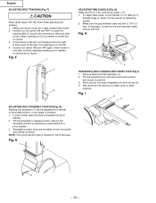
... by tightening socket head bolt in pivot bracket. 3. Quickly turn tracking nut to sand surfaces. F 1 3 2 ADJUSTING BELT ASSEMBLY POSITION (Fig. G) Sanding belt assembly (1) can be within +/-3°. 1. Secure belt assembly position by tightening handle. 2. Secure with bolt. Remove table from idler drum while adjusting belt tracking. 1. F) CAUTION Keep hands away from belt assembly (1). 2. Tilt belt assembly to horizontal position and secure in between table and belt is threaded into dust shroud (3). 4. G 1 ADJUSTING TABLE ANGLE (Fig. To adjust table angle, loosen handle...
... by tightening socket head bolt in pivot bracket. 3. Quickly turn tracking nut to sand surfaces. F 1 3 2 ADJUSTING BELT ASSEMBLY POSITION (Fig. G) Sanding belt assembly (1) can be within +/-3°. 1. Secure belt assembly position by tightening handle. 2. Secure with bolt. Remove table from idler drum while adjusting belt tracking. 1. F) CAUTION Keep hands away from belt assembly (1). 2. Tilt belt assembly to horizontal position and secure in between table and belt is threaded into dust shroud (3). 4. G 1 ADJUSTING TABLE ANGLE (Fig. To adjust table angle, loosen handle...

Instruction Manual
Page 13
...of the belt. Release belt tension by loosening and removing four screws (2). 3. Use mineral spirits to belt (disc). Fig. Remove table assembly. 2. USING MITER GAUGE (Fig. Use miter gauge (1) for beveled work being sanded. After setting miter gauge square to belt (disc), adjust to desired angle by peeling it into place with work stop to position and secure work . J 4 English REPLACING ABRASIVE BELT (Fig. Finish inside of long workpieces with both hands; Move workpiece across abrasive belt. Use a combination square (4) to adjust miter gauge square to remove old...
...of the belt. Release belt tension by loosening and removing four screws (2). 3. Use mineral spirits to belt (disc). Fig. Remove table assembly. 2. USING MITER GAUGE (Fig. Use miter gauge (1) for beveled work being sanded. After setting miter gauge square to belt (disc), adjust to desired angle by peeling it into place with work stop to position and secure work . J 4 English REPLACING ABRASIVE BELT (Fig. Finish inside of long workpieces with both hands; Move workpiece across abrasive belt. Use a combination square (4) to adjust miter gauge square to remove old...
Instruction Manual
Page 14
... further lubrication. • When operation seems stiff, a light coat of dust. KEEP TOOL IN REPAIR • If power cord is frequently vacuumed free of paste wax applied to slip. Use soap and water to order parts. - 14 - English MAINTENANCE GENERAL MAINTENANCE WARNING • For you own safety, turn switch OFF and remove the plug from power source receptacle before maintaining, cleaning, adjusting, or lubricating your sander. • To avoid...
... further lubrication. • When operation seems stiff, a light coat of dust. KEEP TOOL IN REPAIR • If power cord is frequently vacuumed free of paste wax applied to slip. Use soap and water to order parts. - 14 - English MAINTENANCE GENERAL MAINTENANCE WARNING • For you own safety, turn switch OFF and remove the plug from power source receptacle before maintaining, cleaning, adjusting, or lubricating your sander. • To avoid...
Instruction Manual
Page 15
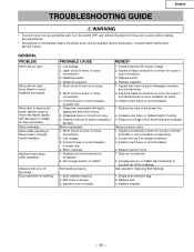
... dust collection bag. 2. English TROUBLESHOOTING GUIDE WARNING • To avoid injury from an accidental start, turn bolt ref. 0032 clockwise. Not tracking properly. Replace switch. 4. Inspect line cord or plug for loose or open connection. 3. Impeller loose or broken. 1. Replace belt. 3. Machine slows down while operating. Applying too much pressure to develop full power (power output of motor decreases rapidly with lights, appliances and other motors. 2. Reduce load...
... dust collection bag. 2. English TROUBLESHOOTING GUIDE WARNING • To avoid injury from an accidental start, turn bolt ref. 0032 clockwise. Not tracking properly. Replace switch. 4. Inspect line cord or plug for loose or open connection. 3. Impeller loose or broken. 1. Replace belt. 3. Machine slows down while operating. Applying too much pressure to develop full power (power output of motor decreases rapidly with lights, appliances and other motors. 2. Reduce load...
Instruction Manual
Page 45
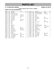
... 0033 0034 0035 0036 0037 0038 0039 0040 0041 0042 0043 0044 0045 Description Set Screw (Headless) Cr. Bolt Fiber Hex Nut Hex Hd. Hd. Screw Platen Pulley Flat Washer Soc. Bolt Pin Drive Drum Set Screw (Headless) Abrasive Belt Bearing Bearing Plate Idler Drum Ass'y Spring Tension Lever Soc. Pan Hd. Pan Hd. Bolt Spring Ball Soc. PARTS LIST 4″ x 8″ BELT/DISC SANDER ALWAYS ORDER BY PART NO. NUMBER.
... 0033 0034 0035 0036 0037 0038 0039 0040 0041 0042 0043 0044 0045 Description Set Screw (Headless) Cr. Bolt Fiber Hex Nut Hex Hd. Hd. Screw Platen Pulley Flat Washer Soc. Bolt Pin Drive Drum Set Screw (Headless) Abrasive Belt Bearing Bearing Plate Idler Drum Ass'y Spring Tension Lever Soc. Pan Hd. Pan Hd. Bolt Spring Ball Soc. PARTS LIST 4″ x 8″ BELT/DISC SANDER ALWAYS ORDER BY PART NO. NUMBER.
Instruction Manual
Page 47
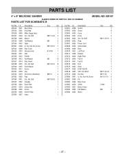
... Bag Clamp Dust Bag Miter Gauge Ass'y Soc. Pan Hd. NUMBER PARTS LIST FOR SCHEMATIC B MODEL NO. Bolt Mount Flat Washer Table Cr. Hd. HD. Bolt Ring Power Cord Strain Relief Body Left Pivot Bracket Right Pivot Foot A Foot B Rod Knob DUST CHUTE SOC. Screw Pin Base Cover V-Belt Motor Pulley Flat Washer Motor Size Qty 1 8 1 2 M8*1.25-10 2 1 1 1 1 1 1 1 2 2 1 1 1 M8*1.25-18 1 M8*1.25 1 M4*0.7-10 6 2 1 Z-630 1 1 M8 2 1 - 47 - AND I.D. Re. PARTS LIST 4″ x 8″ BELT/DISC SANDER ALWAYS...
... Bag Clamp Dust Bag Miter Gauge Ass'y Soc. Pan Hd. NUMBER PARTS LIST FOR SCHEMATIC B MODEL NO. Bolt Mount Flat Washer Table Cr. Hd. HD. Bolt Ring Power Cord Strain Relief Body Left Pivot Bracket Right Pivot Foot A Foot B Rod Knob DUST CHUTE SOC. Screw Pin Base Cover V-Belt Motor Pulley Flat Washer Motor Size Qty 1 8 1 2 M8*1.25-10 2 1 1 1 1 1 1 1 2 2 1 1 1 M8*1.25-18 1 M8*1.25 1 M4*0.7-10 6 2 1 Z-630 1 1 M8 2 1 - 47 - AND I.D. Re. PARTS LIST 4″ x 8″ BELT/DISC SANDER ALWAYS...

Instruction Manual
Page 48
Shinagawa Intercity Tower A, 15-1, Konan 2-chome, Minato-ku, Tokyo 108-6020, Japan Distributed by Hitachi Koki Co., Ltd. C99161861 Printed in China Norcross, GA 30093 Hitachi Koki Canada Co. 6395 Kestrel Road Mississauga ON L5T 1Z5 703 Code No. Issued by Hitachi Koki U.S.A., Ltd. 3950 Steve Reynolds Blvd.
Shinagawa Intercity Tower A, 15-1, Konan 2-chome, Minato-ku, Tokyo 108-6020, Japan Distributed by Hitachi Koki Co., Ltd. C99161861 Printed in China Norcross, GA 30093 Hitachi Koki Canada Co. 6395 Kestrel Road Mississauga ON L5T 1Z5 703 Code No. Issued by Hitachi Koki U.S.A., Ltd. 3950 Steve Reynolds Blvd.

Parts Catalog
Page 2
... 327603 327604 327605 327606 327607 327608 327609 327610 327611 I .D. Screw Platen Pulley Flat Washer Soc. NUMBER. PARTS LIST FOR SCHEMATIC A MODEL NO. Pan Hd. Bolt Hex Nut Pivot Bolt Shaft Base Cover Bracket Hex Nut Wing Screw Soc. Re. Bolt Pin Drive Drum Set Screw (Headless) Abrasive Belt Bearing Bearing Plate Idler Drum Ass'y Spring Tension Lever Soc. Hd. Bolt Guard Size Qty M8*10 3 M5*0.8-10 2 1 1 M8 2 M8*1.25-15...
... 327603 327604 327605 327606 327607 327608 327609 327610 327611 I .D. Screw Platen Pulley Flat Washer Soc. NUMBER. PARTS LIST FOR SCHEMATIC A MODEL NO. Pan Hd. Bolt Hex Nut Pivot Bolt Shaft Base Cover Bracket Hex Nut Wing Screw Soc. Re. Bolt Pin Drive Drum Set Screw (Headless) Abrasive Belt Bearing Bearing Plate Idler Drum Ass'y Spring Tension Lever Soc. Hd. Bolt Guard Size Qty M8*10 3 M5*0.8-10 2 1 1 M8 2 M8*1.25-15...

Parts Catalog
Page 4
... 0050 0051 0052 0053 Description Switch Screw Cover Hook Soc. Screw Pin Base Cover V-Belt Motor Pulley Flat Washer Motor Size Qty 1 8 1 2 M8*1.25-10 2 1 1 1 1 1 1 1 2 2 1 1 1 M8*1.25-18 1 M8*1.25 1 M4*0.7-10 6 2 1 Z-630 1 1 M8 2 1 - 47 - Re. BOLT Hex Nut Cr. Hd. HD. NUMBER PARTS LIST FOR SCHEMATIC B MODEL NO. Screw Disc Cover Abrasive Disc Disc Pointer Flat Washer Disc Guard Soc. PARTS LIST 4″ x 8″ BELT/DISC SANDER ALWAYS ORDER BY PART NO. Bolt Dust Hopper Screw Clip Set Screw (Headless) Pipe Soc.
... 0050 0051 0052 0053 Description Switch Screw Cover Hook Soc. Screw Pin Base Cover V-Belt Motor Pulley Flat Washer Motor Size Qty 1 8 1 2 M8*1.25-10 2 1 1 1 1 1 1 1 2 2 1 1 1 M8*1.25-18 1 M8*1.25 1 M4*0.7-10 6 2 1 Z-630 1 1 M8 2 1 - 47 - Re. BOLT Hex Nut Cr. Hd. HD. NUMBER PARTS LIST FOR SCHEMATIC B MODEL NO. Screw Disc Cover Abrasive Disc Disc Pointer Flat Washer Disc Guard Soc. PARTS LIST 4″ x 8″ BELT/DISC SANDER ALWAYS ORDER BY PART NO. Bolt Dust Hopper Screw Clip Set Screw (Headless) Pipe Soc.


