Instruction Manual
Page 4
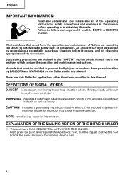
... in death or serious injury. CAUTION indicates a potentially hazardous situation which contain the operation and maintenance instructions. NOTE emphasizes essential information. EXPLANATION OF THE NAILING ACTION OF THE HITACHI NAILER ⅜ This tool has a FULL SEQUENTIAL ACTUATION MECHANISM. English IMPORTANT INFORMATION Read and understand tool labels and all of the operating instructions, safety...
... in death or serious injury. CAUTION indicates a potentially hazardous situation which contain the operation and maintenance instructions. NOTE emphasizes essential information. EXPLANATION OF THE NAILING ACTION OF THE HITACHI NAILER ⅜ This tool has a FULL SEQUENTIAL ACTUATION MECHANISM. English IMPORTANT INFORMATION Read and understand tool labels and all of the operating instructions, safety...
Instruction Manual
Page 13
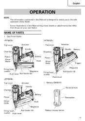
... NOTE: The information contained in the safe operation of the Nailer. NAME OF PARTS 1. Gas Finish Nailer Top cover Actuator Chamber Handle Top cover Chamber Actuator Handle Battery Piston Driver blade Trigger Battery Hook Piston Driver blade Trigger Firing head (outlet) Magazine Push lever Nail feeder (B) Top cover Chamber Actuator Handle Magazine Firing head (outlet...
... NOTE: The information contained in the safe operation of the Nailer. NAME OF PARTS 1. Gas Finish Nailer Top cover Actuator Chamber Handle Top cover Chamber Actuator Handle Battery Piston Driver blade Trigger Battery Hook Piston Driver blade Trigger Firing head (outlet) Magazine Push lever Nail feeder (B) Top cover Chamber Actuator Handle Magazine Firing head (outlet...
Instruction Manual
Page 15
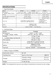
... mm) 3.7 lbs. (1.7 kg) 4.0 lbs. (1.8 kg) 100 nails (1 strip) Intermittent: 2 nails per second Continuous: 1,000 nails per hour EBM315 (1.5 Ah) Li-ion battery, 3.6 V Type No. 728-981......sold separately 3. Gas Finish Nailer Model Dimensions Length × Height × Width Weight Includes battery and fuel cell Nail capacity Cycle rate Battery Fuel Cell NT65GS NT65GB NT65GA 10-1/4" × 11" ×...
... mm) 3.7 lbs. (1.7 kg) 4.0 lbs. (1.8 kg) 100 nails (1 strip) Intermittent: 2 nails per second Continuous: 1,000 nails per hour EBM315 (1.5 Ah) Li-ion battery, 3.6 V Type No. 728-981......sold separately 3. Gas Finish Nailer Model Dimensions Length × Height × Width Weight Includes battery and fuel cell Nail capacity Cycle rate Battery Fuel Cell NT65GS NT65GB NT65GA 10-1/4" × 11" ×...
Instruction Manual
Page 16
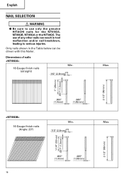
..., leading to use of nails 16 Gauge finish nails (straight) Min. .110" (2.8mm) Max. 2-1/2" (65mm) 1" (25mm) .051" (1.3mm) .055" (1.4mm) .065" (1.65mm) 16 Gauge finish nails (Angle: 20°) Min. .110" (2.8mm) Max. 2-1/2" (65mm) 1-1/4" (32mm) .051" (1.3mm) .055" (1.4mm) .065" (1.65mm) 16 English NAIL SELECTION WARNING ⅷ Be sure to serious injuries. The use only the genuine HITACHI nails for the NT65GS, NT65GB, NT65GA or...
..., leading to use of nails 16 Gauge finish nails (straight) Min. .110" (2.8mm) Max. 2-1/2" (65mm) 1" (25mm) .051" (1.3mm) .055" (1.4mm) .065" (1.65mm) 16 Gauge finish nails (Angle: 20°) Min. .110" (2.8mm) Max. 2-1/2" (65mm) 1-1/4" (32mm) .051" (1.3mm) .055" (1.4mm) .065" (1.65mm) 16 English NAIL SELECTION WARNING ⅷ Be sure to serious injuries. The use only the genuine HITACHI nails for the NT65GS, NT65GB, NT65GA or...

Instruction Manual
Page 18
...up. 1. English ACCESSORIES DANGER ⅷ Accessories other than those shown below can lead to change without any obligation on the part of HITACHI. 2 APPLICATIONS ⅜ Nailing as finishing process for M5 screw 1 8 Nose cap (mounted on tool) (except NT50GS 1 9 Nose cap (mounted on tool) (only... NT50GS 1 0 Case 1 CHARGING METHOD NOTE: Before plugging into the receptacle, make sure the following points. ⅜ The power source voltage is ...
...up. 1. English ACCESSORIES DANGER ⅷ Accessories other than those shown below can lead to change without any obligation on the part of HITACHI. 2 APPLICATIONS ⅜ Nailing as finishing process for M5 screw 1 8 Nose cap (mounted on tool) (except NT50GS 1 9 Nose cap (mounted on tool) (only... NT50GS 1 0 Case 1 CHARGING METHOD NOTE: Before plugging into the receptacle, make sure the following points. ⅜ The power source voltage is ...
Instruction Manual
Page 22
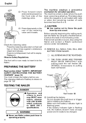
... IMPORTANT SAFETY INSTRUCTIONS FOR BATTERY CHARGER" (page 10). Before actually beginning the nailing work, test the Nailer by using the Nailer and contact a Hitachi authorized service center immediately. (1) REMOVE ALL NAILS, FUEL CELL AND BATTERY FROM NAILER. Ⅺ ALL SCREWS MUST BE TIGHTENED. Ⅺ THE PUSH LEVER AND...battery indicator light is empty. Replace it needs to insert into the Nailer. If gas is not dispersed, fuel cell is flashing green. The fuel cell is flashing red, the battery doesn't have enough power and it . The machine enters a state where the push lever ...
... IMPORTANT SAFETY INSTRUCTIONS FOR BATTERY CHARGER" (page 10). Before actually beginning the nailing work, test the Nailer by using the Nailer and contact a Hitachi authorized service center immediately. (1) REMOVE ALL NAILS, FUEL CELL AND BATTERY FROM NAILER. Ⅺ ALL SCREWS MUST BE TIGHTENED. Ⅺ THE PUSH LEVER AND...battery indicator light is empty. Replace it needs to insert into the Nailer. If gas is not dispersed, fuel cell is flashing green. The fuel cell is flashing red, the battery doesn't have enough power and it . The machine enters a state where the push lever ...
Instruction Manual
Page 24
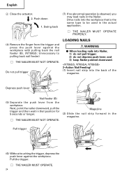
... no abnormal operation is the same type to pulling back nail feeder) Ⅺ THE NAILER MUST NOT OPERATE. Drive nails into the workpiece that position for 5 seconds or longer. Ⅺ THE NAILER MUST NOT OPERATE. Next, point the nailer downward, pull the trigger and then wait in that is... observed, you may load nails in the magazine. Magazine (2) Slide the nail strip forward in the Nailer. Do not pull trigger LOADING NAILS WARNING ⅷ When loading nails into the back of the magazine. Depress push lever Nail feeder (B) (5) Separate the push lever from ...
... no abnormal operation is the same type to pulling back nail feeder) Ⅺ THE NAILER MUST NOT OPERATE. Drive nails into the workpiece that position for 5 seconds or longer. Ⅺ THE NAILER MUST NOT OPERATE. Next, point the nailer downward, pull the trigger and then wait in that is... observed, you may load nails in the magazine. Magazine (2) Slide the nail strip forward in the Nailer. Do not pull trigger LOADING NAILS WARNING ⅷ When loading nails into the back of the magazine. Depress push lever Nail feeder (B) (5) Separate the push lever from ...
Instruction Manual
Page 25
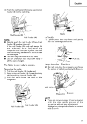
... 3 Nail feeder (B) Nail feeder (A) NOTE: ⅷ Quietly push the nail feeder (A) and nail feeder (B) against the nail, the connecting adhesive of the nail can be damaged. ⅷ Use nail strip of the magazine without any adjustment. The Nailer is now ready to the nail strip. Removing the nails: 1 Pull the nail feeder (B) backward. 2 Return the nail feeder (B) forward quietly while pushing the nail...
... 3 Nail feeder (B) Nail feeder (A) NOTE: ⅷ Quietly push the nail feeder (A) and nail feeder (B) against the nail, the connecting adhesive of the nail can be damaged. ⅷ Use nail strip of the magazine without any adjustment. The Nailer is now ready to the nail strip. Removing the nails: 1 Pull the nail feeder (B) backward. 2 Return the nail feeder (B) forward quietly while pushing the nail...

Instruction Manual
Page 26
...;F MAX (50°C) Keep away from sunshine and from temperature exceeding 120°F (50°C). ⅷ Keep away from trigger when not driving nails to be latched. NAILER OPERATION Read section titled "SAFETY"(pages 5 - 12). The push lever and nose will become hot and get heated up after prolonged or rapid use... and others in presence of flammable liquids or gases. ⅷ Do not touch around the exhaust outlet with bare hands. English Magazine Side guide groove Nail Gap Groove (3) Slide the nail strip into the blade guide.
...;F MAX (50°C) Keep away from sunshine and from temperature exceeding 120°F (50°C). ⅷ Keep away from trigger when not driving nails to be latched. NAILER OPERATION Read section titled "SAFETY"(pages 5 - 12). The push lever and nose will become hot and get heated up after prolonged or rapid use... and others in presence of flammable liquids or gases. ⅷ Do not touch around the exhaust outlet with bare hands. English Magazine Side guide groove Nail Gap Groove (3) Slide the nail strip into the blade guide.

Instruction Manual
Page 27
...32°F (0°C). ⅷ Using the tool for unloaded operation. If pulling the trigger more when not driving nail at too steep of unwanted fastener. This Nailer is depressed (upward position). Explanation of a wall at the same time. next, pull the trigger to oil ...spattering. To continue nailing in use the electrical cord if damaged. Nails can be driven through the wall and hit a person on the opposite side. ⅷ Never use Nailer which is defective or operating abnormally. ⅷ Do not use Nailer as required. 3 2 Push lever Trigger 27 NT65GS, NT65GA, NT65GB ...
...32°F (0°C). ⅷ Using the tool for unloaded operation. If pulling the trigger more when not driving nail at too steep of unwanted fastener. This Nailer is depressed (upward position). Explanation of a wall at the same time. next, pull the trigger to oil ...spattering. To continue nailing in use the electrical cord if damaged. Nails can be driven through the wall and hit a person on the opposite side. ⅷ Never use Nailer which is defective or operating abnormally. ⅷ Do not use Nailer as required. 3 2 Push lever Trigger 27 NT65GS, NT65GA, NT65GB ...
Instruction Manual
Page 28
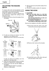
...THE HOOK CAUTION ⅷ If the tool falls, there is a risk that malfunction and/or physical damage can be sure that the Nailer is recommended that each nail penetrates to the same depth, be installed on the other side and securely fasten with screw. ALWAYS WEAR SAFETY GLASSES. If... nails are driven too shallow, turn the adjuster to the Nailer. It is always held firmly against the workpiece. Adjustments are in half-turn increments. 2 Too Deep Turn Adjuster ...
...THE HOOK CAUTION ⅷ If the tool falls, there is a risk that malfunction and/or physical damage can be sure that the Nailer is recommended that each nail penetrates to the same depth, be installed on the other side and securely fasten with screw. ALWAYS WEAR SAFETY GLASSES. If... nails are driven too shallow, turn the adjuster to the Nailer. It is always held firmly against the workpiece. Adjustments are in half-turn increments. 2 Too Deep Turn Adjuster ...
Instruction Manual
Page 29
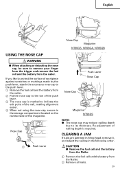
... Lever Nose Cap Nose Cap Magazine NT50GS NOTE: ⅷ The nose cap may reduce nailing depth due to remove your finger from the trigger and remove the fuel cell and the battery from the nailer. If you like to protect the surface of workpiece against scratches or markings made by...in firing head, remove it, and adjust the nailing in the storage compartment located on the reverse side of nailing depth is marked to the push lever. 1 Remove the fuel cell and the battery from the Nailer. 2 Remove all nails. 29 English Nose Cap Magazine NT65GS, NT65GA, NT65GB USING THE NOSE CAP WARNING &#...
... Lever Nose Cap Nose Cap Magazine NT50GS NOTE: ⅷ The nose cap may reduce nailing depth due to remove your finger from the trigger and remove the fuel cell and the battery from the nailer. If you like to protect the surface of workpiece against scratches or markings made by...in firing head, remove it, and adjust the nailing in the storage compartment located on the reverse side of nailing depth is marked to the push lever. 1 Remove the fuel cell and the battery from the Nailer. 2 Remove all nails. 29 English Nose Cap Magazine NT65GS, NT65GA, NT65GB USING THE NOSE CAP WARNING &#...
Instruction Manual
Page 30
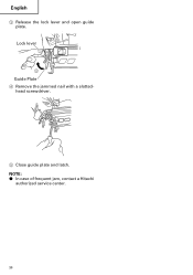
English 3 Release the lock lever and open guide plate. Lock lever 3 Guide Plate 4 Remove the jammed nail with a slottedhead screwdriver. 5 Close guide plate and latch. NOTE: ⅷ In case of frequent jam, contact a Hitachi authorized service center. 30
English 3 Release the lock lever and open guide plate. Lock lever 3 Guide Plate 4 Remove the jammed nail with a slottedhead screwdriver. 5 Close guide plate and latch. NOTE: ⅷ In case of frequent jam, contact a Hitachi authorized service center. 30
Instruction Manual
Page 31
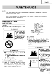
...; When not in use and test in presence of the Nailer. Storing WARNING ⅷ Remove fuel cell, battery and all nails from those on your own Nailer. and 2) clearing a jam. 1. Cloth CAUTION ⅷ Check that differ from Nailer when: 1) doing maintenance and inspection; Lubricate it with fuel... not smooth, nails can be stored in tool case and in a dry place. ⅷ Store indoors at an irregular angle and hurt someone. 2. Some illustrations in this Manual is an aerosol dispensers with Hitachi Gas tool lubricant. DANGER ⅷ Never use , (50°C) the Nailer, fuel cell ...
...; When not in use and test in presence of the Nailer. Storing WARNING ⅷ Remove fuel cell, battery and all nails from those on your own Nailer. and 2) clearing a jam. 1. Cloth CAUTION ⅷ Check that differ from Nailer when: 1) doing maintenance and inspection; Lubricate it with fuel... not smooth, nails can be stored in tool case and in a dry place. ⅷ Store indoors at an irregular angle and hurt someone. 2. Some illustrations in this Manual is an aerosol dispensers with Hitachi Gas tool lubricant. DANGER ⅷ Never use , (50°C) the Nailer, fuel cell ...
Instruction Manual
Page 33
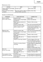
... the driver blade piston is driven. Driver blade worn? Use only recommended nails. Replace ribbon spring. Contact Hitachi for replacement. 33 Replace piston. properly. Operator troubleshooting PROBLEM Nailer operates, but no nail is down or not. Nail feeder (B) worn or damaged? Use only recommended nails. Replace piston ring. Ribbon spring weakened or damaged? Clean and lubricate...
... the driver blade piston is driven. Driver blade worn? Use only recommended nails. Replace ribbon spring. Contact Hitachi for replacement. 33 Replace piston. properly. Operator troubleshooting PROBLEM Nailer operates, but no nail is down or not. Nail feeder (B) worn or damaged? Use only recommended nails. Replace piston ring. Ribbon spring weakened or damaged? Clean and lubricate...
Instruction Manual
Page 34
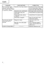
...for returning of the light indicator. Clean as instructed on the maintenance sheet. CORRECTION Push the push lever all the way. Contact Hitachi for replacement. Magazine empty. Check fuel cell, insufficient? Check spark plug wire, worn out? Check the electrical cord. 34 ...Check spark plug, grease or debris? Unable to charge battery. ---------- Load more nails in the magazine. Exchange it doesn't drive a nail or operation unstable. If green: Contact Hitachi for replacement. indicator shows GREEN yet it with a new fuel cell. Note the color of...
...for returning of the light indicator. Clean as instructed on the maintenance sheet. CORRECTION Push the push lever all the way. Contact Hitachi for replacement. Magazine empty. Check fuel cell, insufficient? Check spark plug wire, worn out? Check the electrical cord. 34 ...Check spark plug, grease or debris? Unable to charge battery. ---------- Load more nails in the magazine. Exchange it doesn't drive a nail or operation unstable. If green: Contact Hitachi for replacement. indicator shows GREEN yet it with a new fuel cell. Note the color of...
Instruction Manual
Page 105
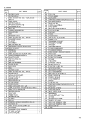
... STOP RUBBER 1 54 NYLON NUT M5 3 55 HITACHI PLATE 1 ITEM NO. BAR WRENCH 3MM 505 NOSE CAP (A) 506 CASE Q'TY 1 1 1 2 2 1 1 1 1 2 2 1 1 1 1 1 1 1 1 1 2 2 1 1 1 1 1 2 1 1 1 1 2 2 1 1 1 1 1 1 1 1 1 1 1 1 2 1 1 1 1 1 1 105 BOLT M4×16 4 14 CHAMBER HEAD 1 15 GASKET 1 16 CHAMBER 1 17 PISTON RING (B) 4 18 RETAINING RING...15 91 ROLL PIN D3×16 92 RIBBON SPRING 93 NAIL FEEDER (B) 94 PRISM 95 CONTROLLER 96 TAPPING SCREW (W/FLANGE) D4×12 97 NAIL RAIL 98 PUSHING SPRING 99 NAIL FEEDER (A) 100 ROLL PIN D2...76 CHAMBER SPRING 77 HEX. SOCKET HD. NT65GS ITEM NO.
... STOP RUBBER 1 54 NYLON NUT M5 3 55 HITACHI PLATE 1 ITEM NO. BAR WRENCH 3MM 505 NOSE CAP (A) 506 CASE Q'TY 1 1 1 2 2 1 1 1 1 2 2 1 1 1 1 1 1 1 1 1 2 2 1 1 1 1 1 2 1 1 1 1 2 2 1 1 1 1 1 1 1 1 1 1 1 1 2 1 1 1 1 1 1 105 BOLT M4×16 4 14 CHAMBER HEAD 1 15 GASKET 1 16 CHAMBER 1 17 PISTON RING (B) 4 18 RETAINING RING...15 91 ROLL PIN D3×16 92 RIBBON SPRING 93 NAIL FEEDER (B) 94 PRISM 95 CONTROLLER 96 TAPPING SCREW (W/FLANGE) D4×12 97 NAIL RAIL 98 PUSHING SPRING 99 NAIL FEEDER (A) 100 ROLL PIN D2...76 CHAMBER SPRING 77 HEX. SOCKET HD. NT65GS ITEM NO.
Instruction Manual
Page 107
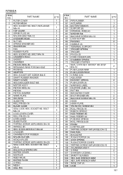
... D3×10 37 LOCK LEVER 38 GUIDE PLATE 39 TAPPING SCREW (W/FLANGE) D4×16 40 HANDLE (B) 41 HEX. SHOULDER BOLT M4×32 42 CYLINDER 43 CHAMBER STOP RUBBER 44 NYLON NUT M5 45 HITACHI PLATE 46 TAPPING SCREW (W/FLANGE) D4×20 47 SEAL LOCK HEX. BAR WRENCH 4MM... PISTON BUMPER 29 NAME PLATE 30 HOUSING 31 GUIDE PIN 32 ROLL PIN D3×16 33 BLADE GUIDE 34 SEAL LOCK HEX. SCREW M4 89 ROLL PIN D3×16 90 RIBBON SPRING 91 NAIL FEEDER (B) 92 NAIL FEEDER (A) 93 PUSHING SPRING 94 ROLL PIN D2.5×26 95 PRISM 96 CONTROLLER 97...
... D3×10 37 LOCK LEVER 38 GUIDE PLATE 39 TAPPING SCREW (W/FLANGE) D4×16 40 HANDLE (B) 41 HEX. SHOULDER BOLT M4×32 42 CYLINDER 43 CHAMBER STOP RUBBER 44 NYLON NUT M5 45 HITACHI PLATE 46 TAPPING SCREW (W/FLANGE) D4×20 47 SEAL LOCK HEX. BAR WRENCH 4MM... PISTON BUMPER 29 NAME PLATE 30 HOUSING 31 GUIDE PIN 32 ROLL PIN D3×16 33 BLADE GUIDE 34 SEAL LOCK HEX. SCREW M4 89 ROLL PIN D3×16 90 RIBBON SPRING 91 NAIL FEEDER (B) 92 NAIL FEEDER (A) 93 PUSHING SPRING 94 ROLL PIN D2.5×26 95 PRISM 96 CONTROLLER 97...
Instruction Manual
Page 109
... BOLT WASHER M5 88 MACHINE SCREW M5×15 89 ROLL PIN D3×16 90 RIBBON SPRING 91 NAIL FEEDER (B) 92 NAIL FEEDER (A) 93 STOPPER SPRING (C) 94 PRISM 95 CONTROLLER 96 TAPPING SCREW (W/FLANGE) D4×12 97 NAIL RAIL 98 ROLL PIN D2.5×26 99 MAGAZINE 100 PUSH STOPPER (B) 101 PUSH... O-RING 501 CHARGER (UC3SML) 502 SAFETY GLASSES 503 HEX. SHOULDER BOLT M4×32 1 42 CYLINDER 1 43 CHAMBER STOP RUBBER 1 44 NYLON NUT M5 3 45 HITACHI PLATE 1 46 SEAL LOCK HEX. BOLT M4×12 3 34 LOCK LEVER COVER 1 35 ROLL PIN D3×10 1 36 LOCK LEVER 1 37 ROLL PIN...
... BOLT WASHER M5 88 MACHINE SCREW M5×15 89 ROLL PIN D3×16 90 RIBBON SPRING 91 NAIL FEEDER (B) 92 NAIL FEEDER (A) 93 STOPPER SPRING (C) 94 PRISM 95 CONTROLLER 96 TAPPING SCREW (W/FLANGE) D4×12 97 NAIL RAIL 98 ROLL PIN D2.5×26 99 MAGAZINE 100 PUSH STOPPER (B) 101 PUSH... O-RING 501 CHARGER (UC3SML) 502 SAFETY GLASSES 503 HEX. SHOULDER BOLT M4×32 1 42 CYLINDER 1 43 CHAMBER STOP RUBBER 1 44 NYLON NUT M5 3 45 HITACHI PLATE 1 46 SEAL LOCK HEX. BOLT M4×12 3 34 LOCK LEVER COVER 1 35 ROLL PIN D3×10 1 36 LOCK LEVER 1 37 ROLL PIN...

Instruction Manual
Page 111
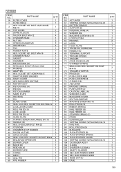
...43 BUFFER COVER 1 44 MUFFLER 1 45 REED VALVE 1 46 BUFFER PLATE 1 47 O-RING 1 48 MESH 1 49 TAPPING SCREW (W/FLANGE) D4×16 2 50 HANDLE (B) 1 51 HEX. BAR WRENCH 4MM 1 505 NOSE CAP (A) 1 506 CASE 1 111 BOLT (W/FLANGE) M5×10 1 4...91 ROLL PIN D3×20 1 92 STOP LEVER 1 93 SPRING 1 94 PLATE 1 90 MAGAZINE 1 96 PRISM 1 97 NAIL FEEDER 1 98 NAIL PLATE 1 99 FEEDER PIECE 1 100 FEED SPRING 1 101 CYLINDER ASS'Y (A) 1 102 CYLINDER HEAD ASS'Y 1 501 CHARGER (... 1 53 CHAMBER STOP RUBBER 1 54 NYLON NUT M5 1 55 HITACHI PLATE 1 ITEM NO. SOCKET HD.
...43 BUFFER COVER 1 44 MUFFLER 1 45 REED VALVE 1 46 BUFFER PLATE 1 47 O-RING 1 48 MESH 1 49 TAPPING SCREW (W/FLANGE) D4×16 2 50 HANDLE (B) 1 51 HEX. BAR WRENCH 4MM 1 505 NOSE CAP (A) 1 506 CASE 1 111 BOLT (W/FLANGE) M5×10 1 4...91 ROLL PIN D3×20 1 92 STOP LEVER 1 93 SPRING 1 94 PLATE 1 90 MAGAZINE 1 96 PRISM 1 97 NAIL FEEDER 1 98 NAIL PLATE 1 99 FEEDER PIECE 1 100 FEED SPRING 1 101 CYLINDER ASS'Y (A) 1 102 CYLINDER HEAD ASS'Y 1 501 CHARGER (... 1 53 CHAMBER STOP RUBBER 1 54 NYLON NUT M5 1 55 HITACHI PLATE 1 ITEM NO. SOCKET HD.


