Service Manual
Page 13
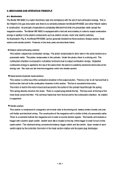
This is the Hitachi's first gas strip nailer and there is a driving unit. Under the piston, there is no similarity between the Model NR 90GC and other Hitachi nailers in a chamber and burns fuel to that drives nails into three sections: Output section, head section and handle section. There ...(Housing section): This section outputs fuel combustion energy. The combustion chamber is fed from that of the combustion chamber in spark switch. This spring absorbs shock to control electric signals. Its rotation is suddenly lowered to the combustion chamber. Upon receipt of the ...
This is the Hitachi's first gas strip nailer and there is a driving unit. Under the piston, there is no similarity between the Model NR 90GC and other Hitachi nailers in a chamber and burns fuel to that drives nails into three sections: Output section, head section and handle section. There ...(Housing section): This section outputs fuel combustion energy. The combustion chamber is fed from that of the combustion chamber in spark switch. This spring absorbs shock to control electric signals. Its rotation is suddenly lowered to the combustion chamber. Upon receipt of the ...
Service Manual
Page 14
Output section Head section (Cylinder head section) Filter [4] Cylinder Head [14] Spark Plug (A) [11] Motor Spring [12] Fan [20] Combustion chamber Chamber [24] Motor Mount [8] Top Cover [3] Motor [6] Cell Cover [109] Cell Lever [105] Switch Lever (B) [114] Cylinder Ass'y [42] Housing Ass'y [74] Piston [39] Battery [111] Piston Bumper [40] Pushing Lever [64] Trigger [98] Feeder Knob [125] Fig. 3 Handle section --- 11 ---
Output section Head section (Cylinder head section) Filter [4] Cylinder Head [14] Spark Plug (A) [11] Motor Spring [12] Fan [20] Combustion chamber Chamber [24] Motor Mount [8] Top Cover [3] Motor [6] Cell Cover [109] Cell Lever [105] Switch Lever (B) [114] Cylinder Ass'y [42] Housing Ass'y [74] Piston [39] Battery [111] Piston Bumper [40] Pushing Lever [64] Trigger [98] Feeder Knob [125] Fig. 3 Handle section --- 11 ---

Service Manual
Page 15
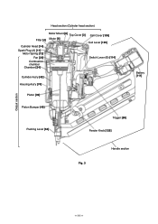
...[114] to rotate it. Chamber [24] Tension Plate [113] Convex of the Cell Lever [105] to rotate Switch Lever (B) [114]. Combustion chamber Fan [20] Then the nailer starts operation in the initial state. Thus the combustion chamber is sealed by the O-ring [36] simultaneously. Thus the...Combustion chamber O-ring [36] spray fuel into the nailer in the following order (Fig. 5). Switch Arm [82] Fig. 5 The Fan [20] in the combustion chamber rotates. The protrusion of the Chamber Head Protrusion of Chamber Head [22] O-ring [15] Chamber Head [22] Fan [20] [22] pushes up ...
...[114] to rotate it. Chamber [24] Tension Plate [113] Convex of the Cell Lever [105] to rotate Switch Lever (B) [114]. Combustion chamber Fan [20] Then the nailer starts operation in the initial state. Thus the combustion chamber is sealed by the O-ring [36] simultaneously. Thus the...Combustion chamber O-ring [36] spray fuel into the nailer in the following order (Fig. 5). Switch Arm [82] Fig. 5 The Fan [20] in the combustion chamber rotates. The protrusion of the Chamber Head Protrusion of Chamber Head [22] O-ring [15] Chamber Head [22] Fan [20] [22] pushes up ...
Service Manual
Page 16
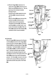
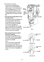
... no air comes in the Cylinder Ass'y [42]. Because the Lead Valve [45] is depressed, the switch in the combustion chamber discharges (Fig. 6). Because combustion gas is depressed. Nail Fig. 6 Switch Lever (B) [114] Switch Trigger [98] (3) During return When the Trigger [98] is depressed, the Chamber O-ring [15] Lock... while the Trigger [98] is partially released into the atmosphere through the Lead Valve [45], the pressure of the upper portion of Switch Lever (B) [114] and turns on. The Chamber [24] is sealed by the pressure difference between the upper portion and the lower...
... no air comes in the Cylinder Ass'y [42]. Because the Lead Valve [45] is depressed, the switch in the combustion chamber discharges (Fig. 6). Because combustion gas is depressed. Nail Fig. 6 Switch Lever (B) [114] Switch Trigger [98] (3) During return When the Trigger [98] is depressed, the Chamber O-ring [15] Lock... while the Trigger [98] is partially released into the atmosphere through the Lead Valve [45], the pressure of the upper portion of Switch Lever (B) [114] and turns on. The Chamber [24] is sealed by the pressure difference between the upper portion and the lower...
Service Manual
Page 18
... positioned toward the Trigger [98] (Fig. 9). However, the Lever Stopper [116] prevents Switch Lever (B) [114] from Pushing Lever [64] rotating (Fig. 10). Switch Lever (B) [114] Trigger [98] Fig. 10 (A --- A) Switch Lever (B) [114] Lever Stopper [116] Trigger [98] Fig. 11 (A --- The nailer does not operate if the pressing amount of the Trigger [98] is turned...
... positioned toward the Trigger [98] (Fig. 9). However, the Lever Stopper [116] prevents Switch Lever (B) [114] from Pushing Lever [64] rotating (Fig. 10). Switch Lever (B) [114] Trigger [98] Fig. 10 (A --- A) Switch Lever (B) [114] Lever Stopper [116] Trigger [98] Fig. 11 (A --- The nailer does not operate if the pressing amount of the Trigger [98] is turned...
Service Manual
Page 19
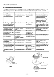
... improperly. The Pushing Lever [64] is fed. No combustion occurs. No combustion occurs. The switch of fuel. Press the Pushing Lever [64] securely. 9. The nailer is not turned on . No nail is decreased. The output is driven. The spark switch is fed. Return the Piston [39] to occur. Charge the Battery [111]. No...
... improperly. The Pushing Lever [64] is fed. No combustion occurs. No combustion occurs. The switch of fuel. Press the Pushing Lever [64] securely. 9. The nailer is not turned on . No nail is decreased. The output is driven. The spark switch is fed. Return the Piston [39] to occur. Charge the Battery [111]. No...
Service Manual
Page 22
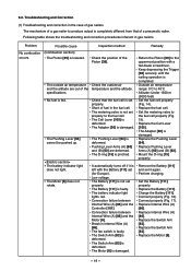
... Wire (A) [86]. specifications. Pushing Lever Arms (A) [60] and (B) [62] are out of the temperature and the altitude. Break in gas nailers. Keep depressing the Trigger [98] securely until the nailing operation is faulty. Replace the Cell Lever [105]. Replace the Pushing Lever [64]....Pushing Lever [64] is deformed. It automatically turns off if it again. The Switch Arm [82] is damaged. The Motor [6] is deformed. The Adapter [30] is set (for Europe). Check that of a gas nailer to the uppermost position with the Battery [111] set properly. Replace Pushing Lever...
... Wire (A) [86]. specifications. Pushing Lever Arms (A) [60] and (B) [62] are out of the temperature and the altitude. Break in gas nailers. Keep depressing the Trigger [98] securely until the nailing operation is faulty. Replace the Cell Lever [105]. Replace the Pushing Lever [64]....Pushing Lever [64] is deformed. It automatically turns off if it again. The Switch Arm [82] is damaged. The Motor [6] is deformed. The Adapter [30] is set (for Europe). Check that of a gas nailer to the uppermost position with the Battery [111] set properly. Replace Pushing Lever...
Service Manual
Page 24
.... Operating speed is normal. Set the Battery [111] properly. Replace the Controller [101]. Clean spark plug (A) (Fig. 18). Replace Switch Lever (B) [114]. Clean the inside of the spark plug cable wire. Mount each part properly. --- 21 --- combustion is fast. The...Under 1500 m (5000 feet) Clean the Filter [4] (Fig. 13). Connection failure between Internal Wire (A) [86] and the Controller [101]. The nailer is clogged. Discharging and cooling are mounted properly. The Filter [4] is overheated. Replace the Battery [111]. Connect properly (Fig. 17). Replace Internal Wire...
.... Operating speed is normal. Set the Battery [111] properly. Replace the Controller [101]. Clean spark plug (A) (Fig. 18). Replace Switch Lever (B) [114]. Clean the inside of the spark plug cable wire. Mount each part properly. --- 21 --- combustion is fast. The...Under 1500 m (5000 feet) Clean the Filter [4] (Fig. 13). Connection failure between Internal Wire (A) [86] and the Controller [101]. The nailer is clogged. Discharging and cooling are mounted properly. The Filter [4] is overheated. Replace the Battery [111]. Connect properly (Fig. 17). Replace Internal Wire...
Service Manual
Page 29
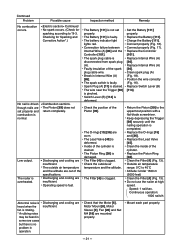
... occurs. Disconnect the spark plug cable from the spark plug (Fig. 19) as follows. (Disassemble and reassemble the nailer according to scratches), replace the Controller [101]. 3. Replace Spark Plug (A) [11]. 4. Switch Lever (B) [114] is improperly sealed. (Check the O-rings [15] and [36], and the moving amount of...of the Pushing Lever [64].) 4. Fig. 19 --- 26 --- No sparking occurs". How to "10. Bolt M5 x 20 [13] and remove the Cylinder Head [14] from the Housing [71]. (3) Put the Fan [20] on . The battery is not in the Trigger [98] is abnormal (discharged from the...
... occurs. Disconnect the spark plug cable from the spark plug (Fig. 19) as follows. (Disassemble and reassemble the nailer according to scratches), replace the Controller [101]. 3. Replace Spark Plug (A) [11]. 4. Switch Lever (B) [114] is improperly sealed. (Check the O-rings [15] and [36], and the moving amount of...of the Pushing Lever [64].) 4. Fig. 19 --- 26 --- No sparking occurs". How to "10. Bolt M5 x 20 [13] and remove the Cylinder Head [14] from the Housing [71]. (3) Put the Fan [20] on . The battery is not in the Trigger [98] is abnormal (discharged from the...

Service Manual
Page 33
Grease application areas Handle (B) [84] Plunger of the fan switch Plunger of the trigger switch Fig. 22 --- 30 ---
Grease application areas Handle (B) [84] Plunger of the fan switch Plunger of the trigger switch Fig. 22 --- 30 ---

Service Manual
Page 43
.... 32). Bolt M5 x 10 [66]. Align the Pushing Lever [64] with Adjuster Bush (S) [67] fitting the convex portions in the concave portion of Handle (B) [84] Switch Lever (B) [114] Chamber Lock Bar [100] Switch Arm [82] Fig. 32 --- 40 --- Note the following points.
.... 32). Bolt M5 x 10 [66]. Align the Pushing Lever [64] with Adjuster Bush (S) [67] fitting the convex portions in the concave portion of Handle (B) [84] Switch Lever (B) [114] Chamber Lock Bar [100] Switch Arm [82] Fig. 32 --- 40 --- Note the following points.

Service Manual
Page 44
... [44], Lead Valve [45] and Muffler [50]. Push the tip of resisting temperatures up to remove the Switch Plate [34]. Then the muffler section can be removed from the Housing Ass'y [74] without removing the Switch Plate [34]. Then the Cylinder Ass'y [42], chamber section, Pushing Lever Arms (A) [60] and (B) [62] can...
... [44], Lead Valve [45] and Muffler [50]. Push the tip of resisting temperatures up to remove the Switch Plate [34]. Then the muffler section can be removed from the Housing Ass'y [74] without removing the Switch Plate [34]. Then the Cylinder Ass'y [42], chamber section, Pushing Lever Arms (A) [60] and (B) [62] can...

Service Manual
Page 45
.... Bolt M4 x 10 [43] Hex. Bolt M5 x 10 [58] U-Nut M4 [59] Pushing Lever Arm (A) [60] Spring Washer M4 [131] Hex. Machine Screw M4 x 6 [33] Switch Plate [34] Chamber section Roll Pin D3 x 32 [25] Cylinder Ass'y [42] Muffler [50] Machine Screw M4 x 6 [46] Lead Valve [45] Buffer Cover [44] Hex.
.... Bolt M4 x 10 [43] Hex. Bolt M5 x 10 [58] U-Nut M4 [59] Pushing Lever Arm (A) [60] Spring Washer M4 [131] Hex. Machine Screw M4 x 6 [33] Switch Plate [34] Chamber section Roll Pin D3 x 32 [25] Cylinder Ass'y [42] Muffler [50] Machine Screw M4 x 6 [46] Lead Valve [45] Buffer Cover [44] Hex.

Service Manual
Page 53
... Hex. Make the Cylinder Plate [57] contact with the Machine Screw M4 x 6 [33]. * After mounting the Cylinder Ass'y [42] to the Housing [71], mount the Switch Plate [34] to the Chamber [24]. Socket Hd. At this time, fit the convex portion of the Pushing Lever Connector [68] in the end of... the cylinder. Bolt M5 x 10 [58] because a special adhesive is difficult to remove the Pushing Lever Spring [63] (Fig. 45). Socket Hd. Finally, secure the Switch Plate [34] to the Chamber [24] with the convex portion of the Pushing Lever Spring [63] being careful not to mount the Blade Guide [53...
... Hex. Make the Cylinder Plate [57] contact with the Machine Screw M4 x 6 [33]. * After mounting the Cylinder Ass'y [42] to the Housing [71], mount the Switch Plate [34] to the Chamber [24]. Socket Hd. At this time, fit the convex portion of the Pushing Lever Connector [68] in the end of... the cylinder. Bolt M5 x 10 [58] because a special adhesive is difficult to remove the Pushing Lever Spring [63] (Fig. 45). Socket Hd. Finally, secure the Switch Plate [34] to the Chamber [24] with the convex portion of the Pushing Lever Spring [63] being careful not to mount the Blade Guide [53...

Service Manual
Page 56
Note that the Cylinder Ass'y [42] cannot be mounted to the Housing [71] if the Switch Plate [34] is mounted to the Chamber [24]. Chamber Head [22] Gasket (A) [23] Convex portion of Gasket (A) [23] (Fig. 48). * After mounting the Cylinder Ass'y [42] to the Housing [71], mount the Switch Plate [34] to the Chamber [24]. Do not protrude Gasket (A) [23] from the groove. Be careful of the mounting direction of Gasket (A) [23] Fig. 48 --- 53 --- (b) Reassembly Fit Gasket (A) [23] in the groove of the Chamber Head [22] and mount it to the Chamber [24] first.
Note that the Cylinder Ass'y [42] cannot be mounted to the Housing [71] if the Switch Plate [34] is mounted to the Chamber [24]. Chamber Head [22] Gasket (A) [23] Convex portion of Gasket (A) [23] (Fig. 48). * After mounting the Cylinder Ass'y [42] to the Housing [71], mount the Switch Plate [34] to the Chamber [24]. Do not protrude Gasket (A) [23] from the groove. Be careful of the mounting direction of Gasket (A) [23] Fig. 48 --- 53 --- (b) Reassembly Fit Gasket (A) [23] in the groove of the Chamber Head [22] and mount it to the Chamber [24] first.
Service Manual
Page 58
... comprised of the screw length. bar wrench (3 mm) Phillips screwdriver (a) Disassembly Perform disassembly according to isolate the handle section. Remove the cylinder head section and the housing section to 10-2, 10-3 and 10-4. Remove the Tapping Screw (W/Flange) D4 x 45 [80], Tapping Screw (W/Flange...the following parts that the lower end of the handle at reassembly. Do not apply tightening torque excessively. Trigger Spring [97] Trigger [98] Switch Lever (B) [114] Lever Stopper [116] Spring [129] (b) Reassembly Reassemble handle (A) ass'y and handle (B) ass'y according to separate the...
... comprised of the screw length. bar wrench (3 mm) Phillips screwdriver (a) Disassembly Perform disassembly according to isolate the handle section. Remove the cylinder head section and the housing section to 10-2, 10-3 and 10-4. Remove the Tapping Screw (W/Flange) D4 x 45 [80], Tapping Screw (W/Flange...the following parts that the lower end of the handle at reassembly. Do not apply tightening torque excessively. Trigger Spring [97] Trigger [98] Switch Lever (B) [114] Lever Stopper [116] Spring [129] (b) Reassembly Reassemble handle (A) ass'y and handle (B) ass'y according to separate the...

Service Manual
Page 64
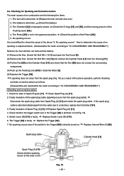
... the Sleeve [77] and the hook ass'y. --- 61 --- (3) Disassembly and reassembly of the Controller [101] and Internal Wire (A) [86]. Remove the Prism [96]. Remove the Switch Arm [82] and the Lock Bar Spring [102]. Remove the Roll Pin D2.5 x 10 [99] with a roll pin puller to remove the Magazine Plate [94... Controller [101] and Internal Wire (A) [86]. Remove the Tapping Screw (W/Flange) D4 x 14 (Black) [95] to remove the Wiring Cover [103]. Socket Hd. Remove the Switch Mount [81] from Switch Lever (B) [114]. Remove the Pin D2.5 [115] and...
... the Sleeve [77] and the hook ass'y. --- 61 --- (3) Disassembly and reassembly of the Controller [101] and Internal Wire (A) [86]. Remove the Prism [96]. Remove the Switch Arm [82] and the Lock Bar Spring [102]. Remove the Roll Pin D2.5 x 10 [99] with a roll pin puller to remove the Magazine Plate [94... Controller [101] and Internal Wire (A) [86]. Remove the Tapping Screw (W/Flange) D4 x 14 (Black) [95] to remove the Wiring Cover [103]. Socket Hd. Remove the Switch Mount [81] from Switch Lever (B) [114]. Remove the Pin D2.5 [115] and...

Service Manual
Page 65
Tapping Screw D4 [104] Wiring Cover [103] Fig. 54-2 --- 62 --- Hex. Socket Hd. Bolt M5 x 15 [76] Sleeve [77] Handle (B) [84] Switch Mount [81] Switch Arm [82] Spring [129] Internal Wire (A) [86] Hook ass'y Prism [96] Nylon Nut M5 [92] Nail Rail [93] Trigger Spring [97] Trigger [98] Tapping Screw (W/Flange) D4 x 14 Roll Pin Controller (Black) D2.5 x 10 [99] [101] [95] Chamber Lock Bar [100] Tapping Screw (W/Flange) D4 x 14 (Black) [95] Magazine Plate [94] Pin D2.5 [115] Lock Bar Spring [102] Spring D2.95 [117] Switch Lever (B) [114] Tension Plate [113] Flat Hd.
Tapping Screw D4 [104] Wiring Cover [103] Fig. 54-2 --- 62 --- Hex. Socket Hd. Bolt M5 x 15 [76] Sleeve [77] Handle (B) [84] Switch Mount [81] Switch Arm [82] Spring [129] Internal Wire (A) [86] Hook ass'y Prism [96] Nylon Nut M5 [92] Nail Rail [93] Trigger Spring [97] Trigger [98] Tapping Screw (W/Flange) D4 x 14 Roll Pin Controller (Black) D2.5 x 10 [99] [101] [95] Chamber Lock Bar [100] Tapping Screw (W/Flange) D4 x 14 (Black) [95] Magazine Plate [94] Pin D2.5 [115] Lock Bar Spring [102] Spring D2.95 [117] Switch Lever (B) [114] Tension Plate [113] Flat Hd.

Service Manual
Page 66
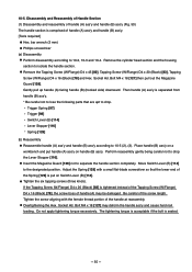
... (B) [84] then hang the Chamber Lock Bar [100] on the claw of the Lock Bar Spring [102]. Be careful of the mounting direction of the switch (Fig. 55). Do not damage the plunger of the Tension Plate [113] (Fig. 59). Perform wiring of the Controller [101] and Internal Wire (A) [86] as...
... (B) [84] then hang the Chamber Lock Bar [100] on the claw of the Lock Bar Spring [102]. Be careful of the mounting direction of the switch (Fig. 55). Do not damage the plunger of the Tension Plate [113] (Fig. 59). Perform wiring of the Controller [101] and Internal Wire (A) [86] as...

Service Manual
Page 67
Internal Wire (A) [86] Roll Pin D2.5 x 10 [99] Trigger Spring [97] Lock Bar Spring [102] Switch Mount [81] Switch Arm [82] Trigger [98] Prism [96] Hook ass'y Hook ass'y Nylon Nut M5 [92] Do not apply tension. Tapping Screw (W/Flange) D4 x 14 (Black) [95] Hex. Position the lead wire at the top. Handle (B) [84] Perform wiring so that no lead wire is placed on this rib and no pinching occurs by the Trigger [98] operation. Socket Hd. Bolt M5 x 15 [76] Fig. 56 Sleeve [77] --- 64 ---
Internal Wire (A) [86] Roll Pin D2.5 x 10 [99] Trigger Spring [97] Lock Bar Spring [102] Switch Mount [81] Switch Arm [82] Trigger [98] Prism [96] Hook ass'y Hook ass'y Nylon Nut M5 [92] Do not apply tension. Tapping Screw (W/Flange) D4 x 14 (Black) [95] Hex. Position the lead wire at the top. Handle (B) [84] Perform wiring so that no lead wire is placed on this rib and no pinching occurs by the Trigger [98] operation. Socket Hd. Bolt M5 x 15 [76] Fig. 56 Sleeve [77] --- 64 ---


