Service Manual
Page 1
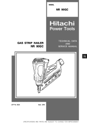
MODEL NR 90GC Hitachi Power Tools GAS STRIP NAILER NR 90GC TECHNICAL DATA AND SERVICE MANUAL N LIST No. E025 Sept. 2005 SPECIFICATIONS AND PARTS ARE SUBJECT TO CHANGE FOR IMPROVEMENT
MODEL NR 90GC Hitachi Power Tools GAS STRIP NAILER NR 90GC TECHNICAL DATA AND SERVICE MANUAL N LIST No. E025 Sept. 2005 SPECIFICATIONS AND PARTS ARE SUBJECT TO CHANGE FOR IMPROVEMENT
Service Manual
Page 13
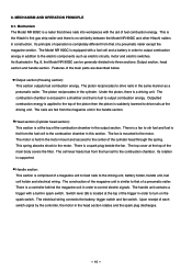
...cylinder. This is the Hitachi's first gas strip nailer and there is located at the top of a pneumatic nailer. The Model NR 90GC is at the top of the trigger in addition to drive nails at the top of the cylinder head through the spring. Head section (Cylinder head section): This section ...a driving unit. Handle section: This section is suddenly lowered to the electric components such as a pneumatic nailer. The handle unit contains a trigger with the aid of the main parts are fed from the fuel cell to the motor. Features of fuel combustion energy. The piston reciprocates in...
...cylinder. This is the Hitachi's first gas strip nailer and there is located at the top of a pneumatic nailer. The Model NR 90GC is at the top of the trigger in addition to drive nails at the top of the cylinder head through the spring. Head section (Cylinder head section): This section ...a driving unit. Handle section: This section is suddenly lowered to the electric components such as a pneumatic nailer. The handle unit contains a trigger with the aid of the main parts are fed from the fuel cell to the motor. Features of fuel combustion energy. The piston reciprocates in...
Service Manual
Page 24
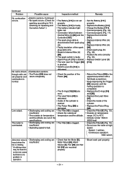
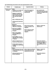
...38]. Continued No spark occurs. (Check for Sparking and Corrective Action".) No nail is not set properly and return completely. The nailer is damaged. Clean the inside of the spark plug cable wire. The Battery [111] is pinched. Low output. Connect properly...the nailing operation is deformed. Outside air temperature range: 0ûC to the uppermost position with a flat-blade screwdriver. Mount each part properly. --- 21 --- Continued Problem Possible cause Inspection method Remedy No combustion occurs. Replace the Lead Valve [45]. combustion is ...
...38]. Continued No spark occurs. (Check for Sparking and Corrective Action".) No nail is not set properly and return completely. The nailer is damaged. Clean the inside of the spark plug cable wire. The Battery [111] is pinched. Low output. Connect properly...the nailing operation is deformed. Outside air temperature range: 0ûC to the uppermost position with a flat-blade screwdriver. Mount each part properly. --- 21 --- Continued Problem Possible cause Inspection method Remedy No combustion occurs. Replace the Lead Valve [45]. combustion is ...
Service Manual
Page 26
... is normally loaded with abnormal nails (bent nails, large or small round-head nails, abnormal collation, etc.). Check if nails (one strip) are fed smoothly into the nail injection port of general-purpose nailers Problem Possible cause Inspection method 1) Nails cannot be driven. Remove the abnormal... Nail Feeder (A) [112]. Remedy Use specified nails. Nail Rail [93] is abnormal (deformed or damaged). Repair or replace the defective part. Foreign matter is found on the nail rail or they need oil. Remove the adhesive fragments and apply oil to the nail feeder, ...
... is normally loaded with abnormal nails (bent nails, large or small round-head nails, abnormal collation, etc.). Check if nails (one strip) are fed smoothly into the nail injection port of general-purpose nailers Problem Possible cause Inspection method 1) Nails cannot be driven. Remove the abnormal... Nail Feeder (A) [112]. Remedy Use specified nails. Nail Rail [93] is abnormal (deformed or damaged). Repair or replace the defective part. Foreign matter is found on the nail rail or they need oil. Remove the adhesive fragments and apply oil to the nail feeder, ...
Service Manual
Page 28
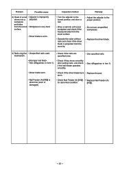
Workpiece is Replace the part. Replace the driver blade. 4) Nails clog the Unspecified nails used. Use specified nails. ... Feeder (A) [112] for abnormal condition. Driver blade is projected from the nose tip. Operate the nailer without nails and check if the driver blade is worn. Check if the nails are specified ones. ...Inspection method Turn the adjuster to the proper position. Problem Possible cause 3) Head of a nail driven into soft wood workpiece and check if the head protrudes from the wood surface. Nail Feeder (A) [112] is improperly adjusted....
Workpiece is Replace the part. Replace the driver blade. 4) Nails clog the Unspecified nails used. Use specified nails. ... Feeder (A) [112] for abnormal condition. Driver blade is projected from the nose tip. Operate the nailer without nails and check if the driver blade is worn. Check if the nails are specified ones. ...Inspection method Turn the adjuster to the proper position. Problem Possible cause 3) Head of a nail driven into soft wood workpiece and check if the head protrudes from the wood surface. Nail Feeder (A) [112] is improperly adjusted....
Service Manual
Page 31
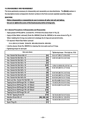
... below correspond to the item numbers in the Parts List and exploded assembly diagram. [CAUTION] Before... 5, 5.1 0.4) 8.3 0.5 (85 5, 6.1 0.4) 1.5 0.5 (15 5, 0.7 0.4) 3.0 0.5 (30 5, 2.2 0.4) 1.0 0.3 (10 3, 0.7 0.2) 1.8 0.4 (18 4, 1.3 0.3) 1.0 0.2 (10 2, 0.7 0.1) --- 28 --- Oil required: Hitachi Gas Nailer Lubricant 8 oz. (250 cc) oil feeder (Code No. 885-246) (Code No. 885-546) Use the cleaner (Code No. 885245) for cleaning the inner...(45 5, 3.4 0.4) 1.0 to 1.5 (10 to 15, 0.7 to tighten the screw of the head securely before driving nails. 10-1. Bolt M5 x 20 13] Hex. Socket Hd. Socket Hd. ...
... below correspond to the item numbers in the Parts List and exploded assembly diagram. [CAUTION] Before... 5, 5.1 0.4) 8.3 0.5 (85 5, 6.1 0.4) 1.5 0.5 (15 5, 0.7 0.4) 3.0 0.5 (30 5, 2.2 0.4) 1.0 0.3 (10 3, 0.7 0.2) 1.8 0.4 (18 4, 1.3 0.3) 1.0 0.2 (10 2, 0.7 0.1) --- 28 --- Oil required: Hitachi Gas Nailer Lubricant 8 oz. (250 cc) oil feeder (Code No. 885-246) (Code No. 885-546) Use the cleaner (Code No. 885245) for cleaning the inner...(45 5, 3.4 0.4) 1.0 to 1.5 (10 to 15, 0.7 to tighten the screw of the head securely before driving nails. 10-1. Bolt M5 x 20 13] Hex. Socket Hd. Socket Hd. ...

Service Manual
Page 37
....) Socket wrench (8 mm (0.314")) (a) Disassembly (See Fig. 26.) Remove the O-ring [15]. bar wrench. Disassembly and Reassembly of Cylinder Head Section (1) Disassembly and reassembly of the Cylinder Head [14], Motor [6] and the related parts [Tools required] Hex. bar wrench (3 mm) Phillips screwdriver Spanner (7 mm (0.276")) x 2 pcs. Remove the Hex. Remove the Roll Pin...
....) Socket wrench (8 mm (0.314")) (a) Disassembly (See Fig. 26.) Remove the O-ring [15]. bar wrench. Disassembly and Reassembly of Cylinder Head Section (1) Disassembly and reassembly of the Cylinder Head [14], Motor [6] and the related parts [Tools required] Hex. bar wrench (3 mm) Phillips screwdriver Spanner (7 mm (0.276")) x 2 pcs. Remove the Hex. Remove the Roll Pin...
Service Manual
Page 40
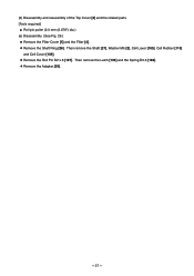
Then remove the Latch [106] and the Spring D3.6 [108]. Remove the Adapter [30]. --- 37 --- Then remove the Shaft [27], Washer M5 [2], Cell Lever [105], Cell Rubber [110] and Cell Cover [109]. Remove the Shaft Ring [26]. Remove the Roll Pin D2 x 8 [107]. (2) Disassembly and reassembly of the Top Cover [3] and the related parts [Tools required] Roll pin puller (2.0 mm (0.078") dia.) (a) Disassembly (See Fig. 29.) Remove the Filter Cover [5] and the Filter [4].
Then remove the Latch [106] and the Spring D3.6 [108]. Remove the Adapter [30]. --- 37 --- Then remove the Shaft [27], Washer M5 [2], Cell Lever [105], Cell Rubber [110] and Cell Cover [109]. Remove the Shaft Ring [26]. Remove the Roll Pin D2 x 8 [107]. (2) Disassembly and reassembly of the Top Cover [3] and the related parts [Tools required] Roll pin puller (2.0 mm (0.078") dia.) (a) Disassembly (See Fig. 29.) Remove the Filter Cover [5] and the Filter [4].

Service Manual
Page 55
Remove the Machine Screw M4 x 6 [33]. Hex. Socket Hd. Bolt M4 x 16 [21]. Then the Chamber Head [22], Gasket (A) [23] and Chamber [24] can be removed. Socket Hd. Then the Chamber Lock Plate [32] can be removed. Bolt M4 x 16 [21] Chamber Head [22] Gasket (A) [23] Chamber [24] Chamber Lock Plate [32] Machine screw M4 x 6 [33] Fig. 47 --- 52 --- (3) Disassembly and reassembly of Chamber [24] and the related parts (Fig. 47) [Tools required] Hex. bar wrench (3 mm (0.118")) Phillips screwdriver (a) Disassembly Remove the Hex.
Remove the Machine Screw M4 x 6 [33]. Hex. Socket Hd. Bolt M4 x 16 [21]. Then the Chamber Head [22], Gasket (A) [23] and Chamber [24] can be removed. Socket Hd. Then the Chamber Lock Plate [32] can be removed. Bolt M4 x 16 [21] Chamber Head [22] Gasket (A) [23] Chamber [24] Chamber Lock Plate [32] Machine screw M4 x 6 [33] Fig. 47 --- 52 --- (3) Disassembly and reassembly of Chamber [24] and the related parts (Fig. 47) [Tools required] Hex. bar wrench (3 mm (0.118")) Phillips screwdriver (a) Disassembly Remove the Hex.
Service Manual
Page 58
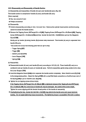
...drop. Bolt M4 x 18 [127] may be damaged. Then handle (A) ass'y is separated from handle (B) ass'y. * Be careful not to lose the following parts that the lower end of the Spring [129] is tightened instead of the Tapping Screw (W/Flange) D4 x 16 (Black) [78], the screw boss of handle...) D4 x 45 [80], Tapping Screw (W/Flange) D4 x 20 (Black) [83], Tapping Screw (W/Flange) D4 x 16 (Black) [78] and Hex. Remove the cylinder head section and the housing section to isolate the handle section. Overtightening the Hex. Adjust the Spring [129] with the female thread portion of the screw...
...drop. Bolt M4 x 18 [127] may be damaged. Then handle (A) ass'y is separated from handle (B) ass'y. * Be careful not to lose the following parts that the lower end of the Spring [129] is tightened instead of the Tapping Screw (W/Flange) D4 x 16 (Black) [78], the screw boss of handle...) D4 x 45 [80], Tapping Screw (W/Flange) D4 x 20 (Black) [83], Tapping Screw (W/Flange) D4 x 16 (Black) [78] and Hex. Remove the cylinder head section and the housing section to isolate the handle section. Overtightening the Hex. Adjust the Spring [129] with the female thread portion of the screw...

Service Manual
Page 60
.... Remove the Roll Pin D4 x 28 [118] in "A" direction as shown in Fig. 52. (2) Disassembly and reassembly of Handle (A) [124], nail feeder and the related parts (Fig. 51) [Tools required] Phillips screwdriver Roll pin puller (4 mm (0.157")) (a) Disassembly Remove the Lever Stopper [116] from the trigger of Handle (A) [124] with a hand...
.... Remove the Roll Pin D4 x 28 [118] in "A" direction as shown in Fig. 52. (2) Disassembly and reassembly of Handle (A) [124], nail feeder and the related parts (Fig. 51) [Tools required] Phillips screwdriver Roll pin puller (4 mm (0.157")) (a) Disassembly Remove the Lever Stopper [116] from the trigger of Handle (A) [124] with a hand...

Service Manual
Page 64
...] from Switch Lever (B) [114]. Tapping Screw D4 [104] to remove the Magazine Plate [94]. Disconnect the connector of Handle (B) [84], Controller [101] and the related parts [Tools required] Spanner Hex. Remove the Roll Pin D2.5 x 10 [99] with a roll pin puller to remove the Controller [101] and Internal Wire (A) [86]. bar...
...] from Switch Lever (B) [114]. Tapping Screw D4 [104] to remove the Magazine Plate [94]. Disconnect the connector of Handle (B) [84], Controller [101] and the related parts [Tools required] Spanner Hex. Remove the Roll Pin D2.5 x 10 [99] with a roll pin puller to remove the Controller [101] and Internal Wire (A) [86]. bar...

Service Manual
Page 66
... the ring of the Roll Pin D2.5 x 10 [99] when mounting the Trigger [98] and Internal Wire (A) [86]. Note the following points. Position the other parts as shown in the reverse order.
... the ring of the Roll Pin D2.5 x 10 [99] when mounting the Trigger [98] and Internal Wire (A) [86]. Note the following points. Position the other parts as shown in the reverse order.

Service Manual
Page 70
After reassembly, rotate the Hook [88] and check that the cross groove of hook and the related parts (Fig. 60) [Tools required] Roll pin puller (4 mm (0.157")) Flat-blade screwdriver (a) Disassembly Remove the Roll Pin D3 x 14 [87]. Roll Pin D3 x 14 [87] ...
After reassembly, rotate the Hook [88] and check that the cross groove of hook and the related parts (Fig. 60) [Tools required] Roll pin puller (4 mm (0.157")) Flat-blade screwdriver (a) Disassembly Remove the Roll Pin D3 x 14 [87]. Roll Pin D3 x 14 [87] ...

Service Manual
Page 75
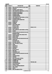
CODE NO. 1 949-665 DESCRIPTION NO. SOCKET HD. USED HEX. SOCKET HD. SOCKET HD. BOLT M5X20 (10 PCS.) 4 14 885-308 CYLINDER HEAD 1 15 885-316 O-RING (I .D. 66.27) 1 37 885-285 RETAINING RING 1 38 885-286 PISTON RING 2 39 885-291 PISTON 1 40 885-289 PISTON BUMPER 1...PLATE SLEEVE 2 55 885-326 SIDE PLATE 1 56 945-255 U-NUT M5 2 57 885-299 CYLINDER PLATE 1 --- 2 --- * ALTERNATIVE PARTS NR 90GC 9 -- 05 SOCKET HD. BOLT M4X16 (10 PCS.) 4 22 885-294 CHAMBER HEAD 1 23 885-295 GASKET (A) 1 24 885-296 CHAMBER 1 25 884-975 ROLL PIN D3X32 2 26 880-319 SHAFT RING...
CODE NO. 1 949-665 DESCRIPTION NO. SOCKET HD. USED HEX. SOCKET HD. SOCKET HD. BOLT M5X20 (10 PCS.) 4 14 885-308 CYLINDER HEAD 1 15 885-316 O-RING (I .D. 66.27) 1 37 885-285 RETAINING RING 1 38 885-286 PISTON RING 2 39 885-291 PISTON 1 40 885-289 PISTON BUMPER 1...PLATE SLEEVE 2 55 885-326 SIDE PLATE 1 56 945-255 U-NUT M5 2 57 885-299 CYLINDER PLATE 1 --- 2 --- * ALTERNATIVE PARTS NR 90GC 9 -- 05 SOCKET HD. BOLT M4X16 (10 PCS.) 4 22 885-294 CHAMBER HEAD 1 23 885-295 GASKET (A) 1 24 885-296 CHAMBER 1 25 884-975 ROLL PIN D3X32 2 26 880-319 SHAFT RING...
Service Manual
Page 76
...USED REMARKS SEAL LOCK HEX. SOCKET HD. BOLT M5X10 (10 PCS.) 1 ADJUSTER BUSH (S) 1 PUSHING LEVER CONNECTOR 1 NAME PLATE 1 SCREW M5 4 HOUSING 1 INSULATOR SHEET 1 HITACHI LABEL 1 HOUSING ASS'Y 1 INCLUD. 70-72 NYLON NUT M4 1 HEX. BOLT M5X15 (10 PCS.) 1 SLEEVE 1 TAPPING SCREW (W/FLANGE) D4X16 (BLACK) 1 WARNING LABEL... ROLL PIN D2.5X10 (10 PCS.) 1 CHAMBER LOCK BAR 1 CONTROLLER 1 CONTROLLER 1 FOR USA, CAN LOCK BAR SPRING 1 WIRING COVER 1 FLAT HD. PARTS ITEM NO. CODE NO. 58 980-046 59 956-329 60 885-302 61 949-812 62 885-303 63 885-305 64 885-271...
...USED REMARKS SEAL LOCK HEX. SOCKET HD. BOLT M5X10 (10 PCS.) 1 ADJUSTER BUSH (S) 1 PUSHING LEVER CONNECTOR 1 NAME PLATE 1 SCREW M5 4 HOUSING 1 INSULATOR SHEET 1 HITACHI LABEL 1 HOUSING ASS'Y 1 INCLUD. 70-72 NYLON NUT M4 1 HEX. BOLT M5X15 (10 PCS.) 1 SLEEVE 1 TAPPING SCREW (W/FLANGE) D4X16 (BLACK) 1 WARNING LABEL... ROLL PIN D2.5X10 (10 PCS.) 1 CHAMBER LOCK BAR 1 CONTROLLER 1 CONTROLLER 1 FOR USA, CAN LOCK BAR SPRING 1 WIRING COVER 1 FLAT HD. PARTS ITEM NO. CODE NO. 58 980-046 59 956-329 60 885-302 61 949-812 62 885-303 63 885-305 64 885-271...

Service Manual
Page 77
... (A) 1 125 885-322 FEEDER KNOB 1 126 302-089 TAPPING SCREW (W/FLANGE) D5X20 (BLACK) 1 127 880-003 HEX. CODE NO. CODE NO. BAR WRENCH 4MM NO. PARTS ITEM NO. CODE NO. USED REMARKS 1 1 FOR USA, CAN 1 --- 4 --- * ALTERNATIVE...
... (A) 1 125 885-322 FEEDER KNOB 1 126 302-089 TAPPING SCREW (W/FLANGE) D5X20 (BLACK) 1 127 880-003 HEX. CODE NO. CODE NO. BAR WRENCH 4MM NO. PARTS ITEM NO. CODE NO. USED REMARKS 1 1 FOR USA, CAN 1 --- 4 --- * ALTERNATIVE...


