
Instruction Manual
Page 3
... use this power tool in a manner that result from power tool operation and maintenance are outlined in the "SAFETY" section of the safety precautions, warnings and operating instructions in this Instruction Manual. Most accidents that has not been specifically recommended by WARNINGS on the power tool and in the Instruction Manual before it occurs, and by the failure to prevent bodily injury or machine damage are identified by HITACHI...
... use this power tool in a manner that result from power tool operation and maintenance are outlined in the "SAFETY" section of the safety precautions, warnings and operating instructions in this Instruction Manual. Most accidents that has not been specifically recommended by WARNINGS on the power tool and in the Instruction Manual before it occurs, and by the failure to prevent bodily injury or machine damage are identified by HITACHI...

Instruction Manual
Page 4
... inattention while operating power tools may ignite the dust of electric shock. 3. Do not wear loose clothing or jewelry. Work Area (1) Keep your hair, clothing and gloves away from heat, oil, sharp edges or moving parts. There is an increased risk of flammable liquids, gases, or dust. Electrical Safety (1) Grounded tools must be caught in moving parts. (3) Avoid accidental starting. If the tools should electrically malfunction or...
... inattention while operating power tools may ignite the dust of electric shock. 3. Do not wear loose clothing or jewelry. Work Area (1) Keep your hair, clothing and gloves away from heat, oil, sharp edges or moving parts. There is an increased risk of flammable liquids, gases, or dust. Electrical Safety (1) Grounded tools must be caught in moving parts. (3) Avoid accidental starting. If the tools should electrically malfunction or...

Instruction Manual
Page 5
... tool's operation. SPECIFIC SAFETY RULES AND SYMBOLS 1. Contact with sharp cutting edges are less likely to high intensity noise can cause hearing loss. 5 Hold tools by qualified repair personnel. A wrench or a key that may contact hidden wiring or its own cord. Such preventive safety measures reduce the risk of starting the tool accidentally. (5) Store idle tools out of reach of parts, and any adjustments, changing accessories, or storing the tool. Keep cutting tools...
... tool's operation. SPECIFIC SAFETY RULES AND SYMBOLS 1. Contact with sharp cutting edges are less likely to high intensity noise can cause hearing loss. 5 Hold tools by qualified repair personnel. A wrench or a key that may contact hidden wiring or its own cord. Such preventive safety measures reduce the risk of starting the tool accidentally. (5) Store idle tools out of reach of parts, and any adjustments, changing accessories, or storing the tool. Keep cutting tools...
Instruction Manual
Page 6
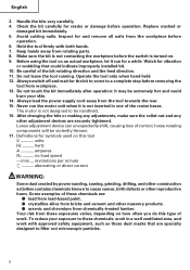
Replace cracked or damaged bit immediately. 5. Before using the tool on how often you do this tool V volts Hz .......... Operate the tool only when hand-held. 12. Loose adjustment device can unexpectedly shift, causing loss of control, loose rotating components will be handheld. 16. hertz A amperes no load speed ---/min ... Your risk from chemically-treated lumber. Check the bit carefully for and remove all nails from...
Replace cracked or damaged bit immediately. 5. Before using the tool on how often you do this tool V volts Hz .......... Operate the tool only when hand-held. 12. Loose adjustment device can unexpectedly shift, causing loss of control, loose rotating components will be handheld. 16. hertz A amperes no load speed ---/min ... Your risk from chemically-treated lumber. Check the bit carefully for and remove all nails from...
Instruction Manual
Page 7
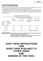
Inspect all electrical cords regularly. Table shows the correct size to use the next heavier gage. SAVE THESE INSTRUCTIONS AND MAKE THEM AVAILABLE TO OTHER USERS AND OWNERS OF THIS TOOL! 7 English USE OF EXTENSION CORD Make sure your product will cause a drop in line voltage resulting in loss of Cord in Feet (Meter) 0 - 25 26 ...electrical shock hazard. The smaller the gage number, the heavier the cord. Ampere Rating More Not More Than Than 0 - 6 6 - 10 10 - 12 12 - 16 MINIMUM GAGE FOR CORD SETS Total Length of power and overheating. If in good condition. Never use...
Inspect all electrical cords regularly. Table shows the correct size to use the next heavier gage. SAVE THESE INSTRUCTIONS AND MAKE THEM AVAILABLE TO OTHER USERS AND OWNERS OF THIS TOOL! 7 English USE OF EXTENSION CORD Make sure your product will cause a drop in line voltage resulting in loss of Cord in Feet (Meter) 0 - 25 26 ...electrical shock hazard. The smaller the gage number, the heavier the cord. Ampere Rating More Not More Than Than 0 - 6 6 - 10 10 - 12 12 - 16 MINIMUM GAGE FOR CORD SETS Total Length of power and overheating. If in good condition. Never use...
Instruction Manual
Page 8
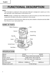
NEVER operate, or attempt any maintenance on your own power tool. NAME OF PARTS Motor Housing Dial Switch Brush Cap Handle Lever 7/8 3/4 5/8 1/2 3/8 1/4 Scale Ring Base Collet Chuck Sub Base SPECIFICATIONS Model Motor Power source Collet chuck capacity Current No-load speed Weight (with cord) Fig. 1 M12VC M12SC Single Phase, Series Commutator Motor Single Phase 120V AC 60 Hz 1/2" (12.7 mm), 1/4" (6.35 mm) 11 A 8000/min - 24000/min 24000/min 7.3 lbs (3.3 kg) 8 English FUNCTIONAL DESCRIPTION...
NEVER operate, or attempt any maintenance on your own power tool. NAME OF PARTS Motor Housing Dial Switch Brush Cap Handle Lever 7/8 3/4 5/8 1/2 3/8 1/4 Scale Ring Base Collet Chuck Sub Base SPECIFICATIONS Model Motor Power source Collet chuck capacity Current No-load speed Weight (with cord) Fig. 1 M12VC M12SC Single Phase, Series Commutator Motor Single Phase 120V AC 60 Hz 1/2" (12.7 mm), 1/4" (6.35 mm) 11 A 8000/min - 24000/min 24000/min 7.3 lbs (3.3 kg) 8 English FUNCTIONAL DESCRIPTION...

Instruction Manual
Page 9
... power tool will start operating immediately and can cause serious injury. 3. If the plug is in the OFF position. Contact a licensed electrician to be repaired. The extension cord should be replaced or repaired. 4. If such a fautly receptacle is far away from the power source, use an extension cord of the environment Confirm that the power source to make appropriate repairs. For example, grooving beveling, cutting...
... power tool will start operating immediately and can cause serious injury. 3. If the plug is in the OFF position. Contact a licensed electrician to be repaired. The extension cord should be replaced or repaired. 4. If such a fautly receptacle is far away from the power source, use an extension cord of the environment Confirm that the power source to make appropriate repairs. For example, grooving beveling, cutting...
Instruction Manual
Page 10
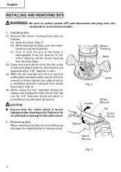
... mm wrench to firmly tighten the collet chuck in a clockwise direction (viewed from under the router). (Fig. 3) (4) When using the 1/4" diameter shank bit, replace the equipped collet chuck with the one for installing bits in damage to the collet chuck. 2. English INSTALLING AND REMOVING BITS WARNING: Be sure to switch power OFF and disconnect the plug from the groove in the motor housing. Lift the motor housing free from the base...
... mm wrench to firmly tighten the collet chuck in a clockwise direction (viewed from under the router). (Fig. 3) (4) When using the 1/4" diameter shank bit, replace the equipped collet chuck with the one for installing bits in damage to the collet chuck. 2. English INSTALLING AND REMOVING BITS WARNING: Be sure to switch power OFF and disconnect the plug from the groove in the motor housing. Lift the motor housing free from the base...
Instruction Manual
Page 11
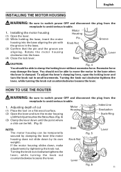
... to clamp the locking lever without excessive force. To adjust the lever's clamping force, open the locking lever and turn the motor housing Scale Ring until the bit just touches the flat surface. (Fig. 5) (3) Clamp the lever down by tightening the knob nut. If the motor housing slides down, make adjustments by its own weight). Adjusting depth of cut (1) Place the tool on a flat wood surface. English INSTALLING THE MOTOR HOUSING WARNING: Be sure to switch power...
... to clamp the locking lever without excessive force. To adjust the lever's clamping force, open the locking lever and turn the motor housing Scale Ring until the bit just touches the flat surface. (Fig. 5) (3) Clamp the lever down by tightening the knob nut. If the motor housing slides down, make adjustments by its own weight). Adjusting depth of cut (1) Place the tool on a flat wood surface. English INSTALLING THE MOTOR HOUSING WARNING: Be sure to switch power...
Instruction Manual
Page 12
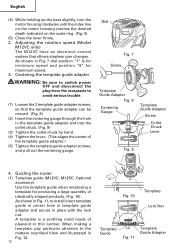
Dial 65 Fig. 7 Screw Template Guide Adapter Fig. 8 Centering Gauge Template Guide Adapter Screw Collet Chuck Lever Fig. 9 4. Guiding the router (1) Template guide (M12VC, M12SC: Optional accessory) Use the template guide when employing a template for maximum speed. 3. Centering the template guide adapter WARNING: Be sure to switch power OFF and disconnect the plug from the receptacle to avoid serious trouble. (1) Loosen the 2 template guide adapter screws, so that allows stepless rpm changes. As shown in Fig. 7 dial...
Dial 65 Fig. 7 Screw Template Guide Adapter Fig. 8 Centering Gauge Template Guide Adapter Screw Collet Chuck Lever Fig. 9 4. Guiding the router (1) Template guide (M12VC, M12SC: Optional accessory) Use the template guide when employing a template for maximum speed. 3. Centering the template guide adapter WARNING: Be sure to switch power OFF and disconnect the plug from the receptacle to avoid serious trouble. (1) Loosen the 2 template guide adapter screws, so that allows stepless rpm changes. As shown in Fig. 7 dial...
Instruction Manual
Page 13
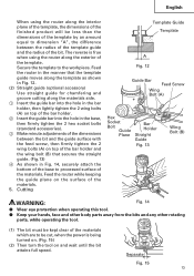
... using the router along the exterior of the template. The reverse is being turned on. (Fig. 15) (2) Then turn the tool on and wait until the bit attains full speed. Cutting Template Guide Template A Fig. 12 Guide Bar Feed Screw Wing Bolt (A) Hex Socket Bolt Guide Plane Bar Holder Straight Guide Fig. 13 Wing Bolt (B) WARNING: Fig. 14 ⅷ Wear eye protection when operating this tool...
... using the router along the exterior of the template. The reverse is being turned on. (Fig. 15) (2) Then turn the tool on and wait until the bit attains full speed. Cutting Template Guide Template A Fig. 12 Guide Bar Feed Screw Wing Bolt (A) Hex Socket Bolt Guide Plane Bar Holder Straight Guide Fig. 13 Wing Bolt (B) WARNING: Fig. 14 ⅷ Wear eye protection when operating this tool...
Instruction Manual
Page 14
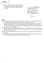
... Fig. 16. Remove the load immediately, and turn the power off, then on the base). Moving the tool forward too slowly may cause the rotation speed to fluctuate. ⅷ When using the straight guide, be sure to install it on the bit size, the kind of workpiece and depth of the workpiece. 14 This will show exactly how the cut . Router feed Router feed workpiece Rotation...
... Fig. 16. Remove the load immediately, and turn the power off, then on the base). Moving the tool forward too slowly may cause the rotation speed to fluctuate. ⅷ When using the straight guide, be sure to install it on the bit size, the kind of workpiece and depth of the workpiece. 14 This will show exactly how the cut . Router feed Router feed workpiece Rotation...
Instruction Manual
Page 15
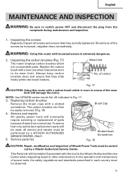
... other maintenance. Replacing carbon brushes Remove the brush caps with a carbon brush which are fully tightened. Service parts list Brush Cap Slotted-head Screwdriver Fig. 18 CAUTION: Repair, modification and inspection of Hitachi Power Tools must be performed by a Hitachi Authorized Service Center. Inspecting the carbon brushes (Fig. 17) The motor employs carbon brushes which is extremely dangerous. 2. Always keep carbon brushes clean and ensure that they are consumable parts. To assure that they slide freely within the brush holders. Inspecting the screws...
... other maintenance. Replacing carbon brushes Remove the brush caps with a carbon brush which are fully tightened. Service parts list Brush Cap Slotted-head Screwdriver Fig. 18 CAUTION: Repair, modification and inspection of Hitachi Power Tools must be performed by a Hitachi Authorized Service Center. Inspecting the carbon brushes (Fig. 17) The motor employs carbon brushes which is extremely dangerous. 2. Always keep carbon brushes clean and ensure that they are consumable parts. To assure that they slide freely within the brush holders. Inspecting the screws...

Instruction Manual
Page 16
... incorporate the latest technological advancements. This Parts List will be carried out by an Hitachi Authorized Service Center. English 6. Service parts list A: Item No. Accordingly, some parts (i.e. In the operation and maintenance of Hitachi Power Tools must be changed without prior notice. 16 C: No. MODIFICATIONS: Hitachi Power Tools are constantly being improved and modified to the Hitachi Authorized Service Center when requesting repair or other maintenance. code numbers and/or design) may be...
... incorporate the latest technological advancements. This Parts List will be carried out by an Hitachi Authorized Service Center. English 6. Service parts list A: Item No. Accordingly, some parts (i.e. In the operation and maintenance of Hitachi Power Tools must be changed without prior notice. 16 C: No. MODIFICATIONS: Hitachi Power Tools are constantly being improved and modified to the Hitachi Authorized Service Center when requesting repair or other maintenance. code numbers and/or design) may be...

Instruction Manual
Page 17
The use Only authorized HITACHI replacement parts and accessories. Model KM12VC, KM12SC (1) 1/4" Collet Chuck (Code No. 323-293) (2) Template Guide Adapter (attaches to change without any other attachment or accessory can be dangerous and could cause injury or mechanical damage. NOTE: Accessories are subject to the router) (Code No. 323-272) (3) Centering Gauge (Code No. 323-296) (4) 16 mm Wrench (Code No. 323-294) (5) 23 mm Wrench (Code No. 323-295) (6) Large...
The use Only authorized HITACHI replacement parts and accessories. Model KM12VC, KM12SC (1) 1/4" Collet Chuck (Code No. 323-293) (2) Template Guide Adapter (attaches to change without any other attachment or accessory can be dangerous and could cause injury or mechanical damage. NOTE: Accessories are subject to the router) (Code No. 323-272) (3) Centering Gauge (Code No. 323-296) (4) 16 mm Wrench (Code No. 323-294) (5) 23 mm Wrench (Code No. 323-295) (6) Large...
Instruction Manual
Page 18
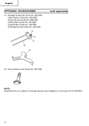
English OPTIONAL ACCESSORIES sold separately (1) Straight Guide Set (Code No. 323-342) 1Bar Holder (Code No. 323-343) 2Feed Screw (Code No. 956-793) 3Wing Bolt (Code No. 301-806) 4Guide Bar (Code No. 323-345) 5Straight Guide (Code No. 323-344) 2 3 1 4 5 (2) Dust Collector Set (Code No. 323-346) NOTE: Specifications are subject to change without any obligation on the part of the HITACHI. 18
English OPTIONAL ACCESSORIES sold separately (1) Straight Guide Set (Code No. 323-342) 1Bar Holder (Code No. 323-343) 2Feed Screw (Code No. 956-793) 3Wing Bolt (Code No. 301-806) 4Guide Bar (Code No. 323-345) 5Straight Guide (Code No. 323-344) 2 3 1 4 5 (2) Dust Collector Set (Code No. 323-346) NOTE: Specifications are subject to change without any obligation on the part of the HITACHI. 18

Parts List
Page 2
CODE NO. 1 DESCRIPTION NO. USED MODEL DS 18DVB CORDLESS DRIVER DRILL 1 2 MODEL C 6DD CORDLESS CIRCULAR SAW 1 3 MODEL CR 18DV CORDLESS SABER SAW 1 4 MODEL UC 24YFA CHARGER 1 5 MODEL UB 18D CORDLESS TORCHLIGHT 1 6 322-376 BAG 1 REMARKS KC 18DG --- 2 --- * ALTERNATIVE PARTS Printed in Japan 11 -- 03 (031110N) PARTS ITEM NO.
CODE NO. 1 DESCRIPTION NO. USED MODEL DS 18DVB CORDLESS DRIVER DRILL 1 2 MODEL C 6DD CORDLESS CIRCULAR SAW 1 3 MODEL CR 18DV CORDLESS SABER SAW 1 4 MODEL UC 24YFA CHARGER 1 5 MODEL UB 18D CORDLESS TORCHLIGHT 1 6 322-376 BAG 1 REMARKS KC 18DG --- 2 --- * ALTERNATIVE PARTS Printed in Japan 11 -- 03 (031110N) PARTS ITEM NO.


