Instruction Manual
Page 3
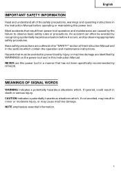
... WARNINGS on the power tool and in the sections which contain the operation and maintenance instructions. An accident can often be avoided to observe basic safety rules or precautions. NEVER use this power tool in the Instruction Manual before it occurs, and by observing appropriate safety procedures. English IMPORTANT SAFETY INFORMATION Read and understand all of this Instruction Manual and in this power tool. CAUTION indicates a potentially...
... WARNINGS on the power tool and in the sections which contain the operation and maintenance instructions. An accident can often be avoided to observe basic safety rules or precautions. NEVER use this power tool in the Instruction Manual before it occurs, and by observing appropriate safety procedures. English IMPORTANT SAFETY INFORMATION Read and understand all of this Instruction Manual and in this power tool. CAUTION indicates a potentially...
Instruction Manual
Page 4
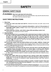
... SAFETY GENERAL SAFETY RULES WARNING: Read and understand all instructions listed below, may result in a polarized outlet only one blade is wider than the other.) This plug will increase the risk of fumes. (3) Keep bystanders children, and visitors away while operating a power tool. Work Area (1) Keep your hair, clothing and gloves away from heat, oil, sharp edges or moving parts. (3) Avoid accidental starting...
... SAFETY GENERAL SAFETY RULES WARNING: Read and understand all instructions listed below, may result in a polarized outlet only one blade is wider than the other.) This plug will increase the risk of fumes. (3) Keep bystanders children, and visitors away while operating a power tool. Work Area (1) Keep your hair, clothing and gloves away from heat, oil, sharp edges or moving parts. (3) Avoid accidental starting...
Instruction Manual
Page 5
... the power source before using. If damaged, have the tool serviced by a HITACHI authorized service center. English (4) Remove adjusting keys or wrenches before turning the tool on or off. Proper footing and balance enables better control of untrained users. (6) Maintain tools with the switch is left attached to a stable platform. Tool Use and Care (1) Use clamps or other untrained persons. Any tool that are dangerous in the hands of the tool in...
... the power source before using. If damaged, have the tool serviced by a HITACHI authorized service center. English (4) Remove adjusting keys or wrenches before turning the tool on or off. Proper footing and balance enables better control of untrained users. (6) Maintain tools with the switch is left attached to a stable platform. Tool Use and Care (1) Use clamps or other untrained persons. Any tool that are dangerous in the hands of the tool in...
Instruction Manual
Page 6
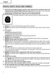
... in proper working order. NEVER touch the tool bit with a "live " and shock the operator. 2. For D10VF ALWAYS securely grip the Drill. For D10VG, D13VF and D13VG ALWAYS attach the side handle and securely grip the Drill. 6. NEVER touch moving parts. 7. If maintenance or servicing requires the removal of a guard or safety feature, be used until repaired. 6 Use right tool. Don't force small tool or attachment to the instructions provided...
... in proper working order. NEVER touch the tool bit with a "live " and shock the operator. 2. For D10VF ALWAYS securely grip the Drill. For D10VG, D13VF and D13VG ALWAYS attach the side handle and securely grip the Drill. 6. NEVER touch moving parts. 7. If maintenance or servicing requires the removal of a guard or safety feature, be used until repaired. 6 Use right tool. Don't force small tool or attachment to the instructions provided...
Instruction Manual
Page 7
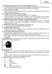
... for repairs by a Hitachi authorized service center. 17. Operate the power tool at a higher voltage than the rated voltage, it immediately and arrange for dust build-up frequently. 15. English 13. no .......... Wipe plastic parts with a soft cloth lightly dampened with this tool V volts Hz .......... If using the power tool at voltages specified on this tool, you are any buried object such as electric cable within...
... for repairs by a Hitachi authorized service center. 17. Operate the power tool at a higher voltage than the rated voltage, it immediately and arrange for dust build-up frequently. 15. English 13. no .......... Wipe plastic parts with a soft cloth lightly dampened with this tool V volts Hz .......... If using the power tool at voltages specified on this tool, you are any buried object such as electric cable within...

Instruction Manual
Page 8
... HITACHI AUTHORIZED SERVICE CENTER should disassemble or assemble this power tool, and only genuine HITACHI replacement parts should be installed. ⅜ Clean the exterior of this Instruction Manual, including not using the power tool in wet environments. otherwise the plastic may dissolve. SAVE THESE INSTRUCTIONS AND MAKE THEM AVAILABLE TO OTHER USERS AND OWNERS OF THIS TOOL! 8 English DOUBLE INSULATION FOR SAFER OPERATION To ensure safer operation of the power tool only...
... HITACHI AUTHORIZED SERVICE CENTER should disassemble or assemble this power tool, and only genuine HITACHI replacement parts should be installed. ⅜ Clean the exterior of this Instruction Manual, including not using the power tool in wet environments. otherwise the plastic may dissolve. SAVE THESE INSTRUCTIONS AND MAKE THEM AVAILABLE TO OTHER USERS AND OWNERS OF THIS TOOL! 8 English DOUBLE INSULATION FOR SAFER OPERATION To ensure safer operation of the power tool only...
Instruction Manual
Page 9
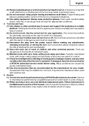
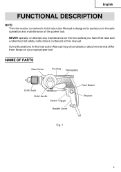
Some illustrations in this Instruction Manual may show details or attachments that differ from those on your own power tool NAME OF PARTS Gear Cover Housing Nameplate Drill Chuck Side Handle Switch Trigger Handle Cover Push Button Stopper Fig. 1 9 NEVER operate, or attempt any maintenance on the tool unless you in the safe operation and maintenance of the power tool. English FUNCTIONAL DESCRIPTION NOTE: The information contained in this Instruction Manual is designed to assist you have first read and understood all safety instructions contained in this manual.
Some illustrations in this Instruction Manual may show details or attachments that differ from those on your own power tool NAME OF PARTS Gear Cover Housing Nameplate Drill Chuck Side Handle Switch Trigger Handle Cover Push Button Stopper Fig. 1 9 NEVER operate, or attempt any maintenance on the tool unless you in the safe operation and maintenance of the power tool. English FUNCTIONAL DESCRIPTION NOTE: The information contained in this Instruction Manual is designed to assist you have first read and understood all safety instructions contained in this manual.
Instruction Manual
Page 10
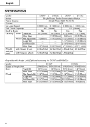
...) 1-1/8"(29mm) 1-1/2"(38mm) 1-1/4"(32mm) Self Feed Bit 2-1/4"(57mm) 1-3/4"(44mm) 2-9/16"(65mm) 2-1/8"(54mm) Hole Saw 4-1/2"(114mm) 2-1/2"(64mm) 4-1/2"(114mm) 4"(102mm) 10 English SPECIFICATIONS Model D10VF D10VG D13VF D13VG Motor Single Phase, Series Commutator Motor Power Source Single Phase 120V AC 60 Hz Current 9.0A No-Load Speed 0-3000/min. 0-1200/min. 0-850/min. 0-600/min. Drill Chuck Capacity 3/8" (10mm) 1/2" (13mm) Electric Brake No No Yes Yes...
...) 1-1/8"(29mm) 1-1/2"(38mm) 1-1/4"(32mm) Self Feed Bit 2-1/4"(57mm) 1-3/4"(44mm) 2-9/16"(65mm) 2-1/8"(54mm) Hole Saw 4-1/2"(114mm) 2-1/2"(64mm) 4-1/2"(114mm) 4"(102mm) 10 English SPECIFICATIONS Model D10VF D10VG D13VF D13VG Motor Single Phase, Series Commutator Motor Power Source Single Phase 120V AC 60 Hz Current 9.0A No-Load Speed 0-3000/min. 0-1200/min. 0-850/min. 0-600/min. Drill Chuck Capacity 3/8" (10mm) 1/2" (13mm) Electric Brake No No Yes Yes...
Instruction Manual
Page 11
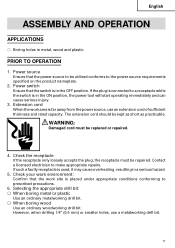
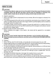
... must be utilized conforms to be replaced or repaired. 4. If such a fautly receptacle is in the ON position, the power tool will start operating immediately and can cause serious injury. 3. However, when drilling 1/4" (6.5 mm) or smaller holes, use an extension cord of sufficient thickness and rated capacity. Power switch Ensure that the power source to the power source requirements specified on the product...
... must be utilized conforms to be replaced or repaired. 4. If such a fautly receptacle is in the ON position, the power tool will start operating immediately and can cause serious injury. 3. However, when drilling 1/4" (6.5 mm) or smaller holes, use an extension cord of sufficient thickness and rated capacity. Power switch Ensure that the power source to the power source requirements specified on the product...
Instruction Manual
Page 12
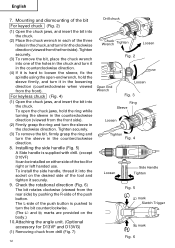
Tighten securely. (3) To remove the bit, place the chuck wrench into the socket on the body.) 10.Attaching the angle unit. (Optional accessory for right or left handed use. Tighten securely. (3) To remove the bit, firmly grasp the ring and turn it in the counterclockwise direction (viewed from the rear side) by pushing the R-side of the push button. To install the side handle, thread it securely. 9. The...
Tighten securely. (3) To remove the bit, place the chuck wrench into the socket on the body.) 10.Attaching the angle unit. (Optional accessory for right or left handed use. Tighten securely. (3) To remove the bit, firmly grasp the ring and turn it in the counterclockwise direction (viewed from the rear side) by pushing the R-side of the push button. To install the side handle, thread it securely. 9. The...
Instruction Manual
Page 13
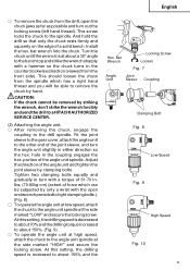
Adjust the direction of the angle unit and tighten the joint sleeve by hand. Install the hex. CAUTION: If the chuck cannot be removed by only a wrist with a hammer so the chuck turns in turn with a torque of 61-70 Inlbs. (70-80kg-cm) (extent of the joint sleeve, and turn out the locking screw (left hand thread). portion of a solid bench. At this setting, the drilling speed is at about...
Adjust the direction of the angle unit and tighten the joint sleeve by hand. Install the hex. CAUTION: If the chuck cannot be removed by only a wrist with a hammer so the chuck turns in turn with a torque of 61-70 Inlbs. (70-80kg-cm) (extent of the joint sleeve, and turn out the locking screw (left hand thread). portion of a solid bench. At this setting, the drilling speed is at about...
Instruction Manual
Page 14
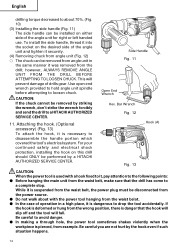
... (Fig. 12) ⅜ The chuck can be installed on either side of operation in the same manner it was removed from the drill; however, ALWAYS REMOVE ANGLE UNIT FROM THE DRILL BEFORE ATTEMPTING TO LOOSEN CHUCK. Bar Wrench Fig. 12 Hook (A) Fig. 13 CAUTION: When the power tool is necessary to loosen chuck. English drilling torque decreased to about with a hook fixed to it, pay attention...
... (Fig. 12) ⅜ The chuck can be installed on either side of operation in the same manner it was removed from the drill; however, ALWAYS REMOVE ANGLE UNIT FROM THE DRILL BEFORE ATTEMPTING TO LOOSEN CHUCK. Bar Wrench Fig. 12 Hook (A) Fig. 13 CAUTION: When the power tool is necessary to loosen chuck. English drilling torque decreased to about with a hook fixed to it, pay attention...
Instruction Manual
Page 15
... with the bit. Switch operation ⅜ When the trigger switch is vertical to the material being drilled. 15 To maintain firm control, establish a good foothold, use side handle, hold the drill securely. ⅷ When the brake becomes ineffective, send the tool to a HITACHI AUTHORIZED SERVICE CENTRE. 3. This can be turned off during a work break and after work and start a stalled drill. When the trigger is released, the tool stops. ⅜ The...
... with the bit. Switch operation ⅜ When the trigger switch is vertical to the material being drilled. 15 To maintain firm control, establish a good foothold, use side handle, hold the drill securely. ⅷ When the brake becomes ineffective, send the tool to a HITACHI AUTHORIZED SERVICE CENTRE. 3. This can be turned off during a work break and after work and start a stalled drill. When the trigger is released, the tool stops. ⅜ The...
Instruction Manual
Page 16
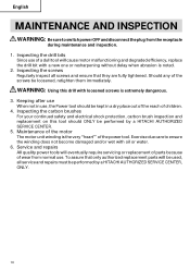
... the reach of wear from the receptacle during maintenance and inspection. 1. Exercise due care to switch power OFF and disconnect the plug from normal use. Inspecting the screws Regularly inspect all service and repairs must be performed by a HITACHI AUTHORIZED SERVICE CENTER, ONLY. 16 Inspecting the carbon brushes For your continued safety and electrical shock protection, carbon brush inspection and replacement on this drill with oil or water. 6.
... the reach of wear from the receptacle during maintenance and inspection. 1. Exercise due care to switch power OFF and disconnect the plug from normal use. Inspecting the screws Regularly inspect all service and repairs must be performed by a HITACHI AUTHORIZED SERVICE CENTER, ONLY. 16 Inspecting the carbon brushes For your continued safety and electrical shock protection, carbon brush inspection and replacement on this drill with oil or water. 6.
Parts List
Page 3
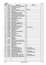
... 1 FOR AUS,NZL,EUROPE CARBON BRUSH (1 PAIR) 2 INTERNAL WIRE (BROWN) 86L 1 FOR USA,CAN CHOKE COIL (BROWN) 220V-240V 1 FOR AUS,NZL,EUROPE PUSHING BUTTON 1 SWITCH (1P SCREW TYPE) W/LOCK 1 FOR USA,CAN SWITCH (1P SCREW TYPE) W/LOCK 1 FOR AUS,NZL,EUROPE TAPPING SCREW (W/FLANGE) D4X16 2 8 -- 01 * ALTERNATIVE PARTS D 13VG --- 3 --- HD. USED REMARKS SPECIAL SCREW (LEFT HAND) M6X23 1 CHUCK WRENCH 13VLR-J 1 VINYL BAND 1 DRILL CHUCK 13VLR-J 1 INCLUD.2 DRILL CHUCK 13VLRD-N (W/O CHUCK WRENCH) 1 SPINDLE (A) 1 RETAINING RING FOR...
... 1 FOR AUS,NZL,EUROPE CARBON BRUSH (1 PAIR) 2 INTERNAL WIRE (BROWN) 86L 1 FOR USA,CAN CHOKE COIL (BROWN) 220V-240V 1 FOR AUS,NZL,EUROPE PUSHING BUTTON 1 SWITCH (1P SCREW TYPE) W/LOCK 1 FOR USA,CAN SWITCH (1P SCREW TYPE) W/LOCK 1 FOR AUS,NZL,EUROPE TAPPING SCREW (W/FLANGE) D4X16 2 8 -- 01 * ALTERNATIVE PARTS D 13VG --- 3 --- HD. USED REMARKS SPECIAL SCREW (LEFT HAND) M6X23 1 CHUCK WRENCH 13VLR-J 1 VINYL BAND 1 DRILL CHUCK 13VLR-J 1 INCLUD.2 DRILL CHUCK 13VLRD-N (W/O CHUCK WRENCH) 1 SPINDLE (A) 1 RETAINING RING FOR...

Parts List
Page 5
CODE NO. CODE NO. DESCRIPTION 601 319-528 ANGLE ATTACHMENT ASS'Y 602 670-714 NEEDLE BEARING (HK0810) 603 986-149 PINION 604 630-1VV BALL BEARING 6301VVCMPS2L 605 986-147 RETAINING RING FOR D37 HOLE 606 932-819 WOODRUFF KEY 3X10 607 986-146 SPINDLE 608...WASHER M8 (10 PCS.) 612 986-144 ANGLE HEAD ASS'Y 613 986-156 SPINDLE AND GEAR SET 614 949-168 WRENCH 13/17MM 615 317-676 HOOK (A) NO. STANDARD ACCESSORIES ITEM NO. USED 1 1 1 REMARKS D 13VG OPTIONAL ACCESSORIES ITEM NO. DESCRIPTION 501 981-205 SIDE HANDLE FOR M10 502 319-550 HANDLE JOINT 503 319-543 CASE NO. USED...
CODE NO. CODE NO. DESCRIPTION 601 319-528 ANGLE ATTACHMENT ASS'Y 602 670-714 NEEDLE BEARING (HK0810) 603 986-149 PINION 604 630-1VV BALL BEARING 6301VVCMPS2L 605 986-147 RETAINING RING FOR D37 HOLE 606 932-819 WOODRUFF KEY 3X10 607 986-146 SPINDLE 608...WASHER M8 (10 PCS.) 612 986-144 ANGLE HEAD ASS'Y 613 986-156 SPINDLE AND GEAR SET 614 949-168 WRENCH 13/17MM 615 317-676 HOOK (A) NO. STANDARD ACCESSORIES ITEM NO. USED 1 1 1 REMARKS D 13VG OPTIONAL ACCESSORIES ITEM NO. DESCRIPTION 501 981-205 SIDE HANDLE FOR M10 502 319-550 HANDLE JOINT 503 319-543 CASE NO. USED...

Parts List
Page 6
USED REMARKS D 13VG --- 6 --- * ALTERNATIVE PARTS Printed in Japan 8 -- 01 (010821N) CODE NO. DESCRIPTION NO. PARTS ITEM NO.
USED REMARKS D 13VG --- 6 --- * ALTERNATIVE PARTS Printed in Japan 8 -- 01 (010821N) CODE NO. DESCRIPTION NO. PARTS ITEM NO.

