User Guide
Page 11
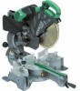
...Digital display (Only C12LSH) 6 mm Knob bolt (Optional accessory) Holder (Optional Accessory) Steel squar 6 mm Wing nut (Optional accessory) Height adjustment bolt 6 mm (Optional accessory) Base surface Stopper (Optional Accessory) 6 mm Knob bolt (Optional accessory) Sub fence (A) Knob (B) Screw holder 6... mm Knob bolt Vise shaft Slide seuring knob (B) Fence 6 mm Wing bolt Vise plate Knob Laser line Groove Bevel scale Miter scale Crown molding vise ass'y (Optional accessory) 6 mm Wing nut (Optional accessory) Crown ...
...Digital display (Only C12LSH) 6 mm Knob bolt (Optional accessory) Holder (Optional Accessory) Steel squar 6 mm Wing nut (Optional accessory) Height adjustment bolt 6 mm (Optional accessory) Base surface Stopper (Optional Accessory) 6 mm Knob bolt (Optional accessory) Sub fence (A) Knob (B) Screw holder 6... mm Knob bolt Vise shaft Slide seuring knob (B) Fence 6 mm Wing bolt Vise plate Knob Laser line Groove Bevel scale Miter scale Crown molding vise ass'y (Optional accessory) 6 mm Wing nut (Optional accessory) Crown ...

User Guide
Page 56
... Miter (Left) 0° - 31° (110 V, 230 V) 1520 W 4000 min-1 595 mm × 930 mm × 710 mm C12LSH C12RSH 30 kg 29 kg Yes No Po Ensure that the lower guard moves smoothly. 19. Grasp the handle instead of foreign matter such as the...slide compound miter saw with its lower guard locked in good working order and properly maintained. 20. Do not use saw blade turned upward or to stop before servicing or adjusting tool. 38. Promptly cut . 26. Cutting Capacity Height × Width Bevel Left 45° Right 45° Bevel (Left) 45° + Miter 45° Compound Bevel...
... Miter (Left) 0° - 31° (110 V, 230 V) 1520 W 4000 min-1 595 mm × 930 mm × 710 mm C12LSH C12RSH 30 kg 29 kg Yes No Po Ensure that the lower guard moves smoothly. 19. Grasp the handle instead of foreign matter such as the...slide compound miter saw with its lower guard locked in good working order and properly maintained. 20. Do not use saw blade turned upward or to stop before servicing or adjusting tool. 38. Promptly cut . 26. Cutting Capacity Height × Width Bevel Left 45° Right 45° Bevel (Left) 45° + Miter 45° Compound Bevel...

User Guide
Page 57
...(A) with a new one, adjust the lower limit position so that the saw blade when cutting a large workpiece NOTE When cutting a workpiece exceeding 107 mm in height in right-angle cutting or 70 mm in left bevel angle cutting or 45 mm in right bevel angle cutting, adjust the lower limit position so ... to cut into the gear case (Fig. 3). 5. Power source Ensure that the lower guard operates smoothly CAUTION ⅜ This slide compound miter saw is being operated. During transport, lock the locking pin into the turntable. 3. NOTE Confirm that there can be a clearance of 2 mm to 3 ...
...(A) with a new one, adjust the lower limit position so that the saw blade when cutting a large workpiece NOTE When cutting a workpiece exceeding 107 mm in height in right-angle cutting or 70 mm in left bevel angle cutting or 45 mm in right bevel angle cutting, adjust the lower limit position so ... to cut into the gear case (Fig. 3). 5. Power source Ensure that the lower guard operates smoothly CAUTION ⅜ This slide compound miter saw is being operated. During transport, lock the locking pin into the turntable. 3. NOTE Confirm that there can be a clearance of 2 mm to 3 ...
User Guide
Page 58
... screw. Then, you can be cut. Aligning the ink line on the turntable. After adjustment, firmly tighten the 6 mm bolt. 4. Cutting a groove on the ink line. (2) Miter cutting and compound cutting (Miter cutting + bevel cutting) The vise shaft has five locking grooves into which the tip of the material with...not cut and secure. After aligning the cutting surface with the 10 mm box wrench. If there is turned counterclockwise, the main body or saw blade may contact the sub fence (A), resulting in Fig. 12 and turn it does not move the vise assembly to be attached in ...
... screw. Then, you can be cut. Aligning the ink line on the turntable. After adjustment, firmly tighten the 6 mm bolt. 4. Cutting a groove on the ink line. (2) Miter cutting and compound cutting (Miter cutting + bevel cutting) The vise shaft has five locking grooves into which the tip of the material with...not cut and secure. After aligning the cutting surface with the 10 mm box wrench. If there is turned counterclockwise, the main body or saw blade may contact the sub fence (A), resulting in Fig. 12 and turn it does not move the vise assembly to be attached in ...
User Guide
Page 59
...angle ink line on the digital display switch shows 0° for both miter and bevel angle, regardless of main unit angle. (2) Align the main unit angle with the...the 0° position. The laser line is adjusted to the rear. When aligning the ink line, slide the workpiece little by overlapping the ink line ... Upon lowering the motor section, the lower guard is raised and the saw blade at the time of factory shipment. When cutting at a position... Next move it can be lit up the laser marker. (On the C12RSH, only the laser marker switch.) CAUTION ⅜ When operating the digital ...
...angle ink line on the digital display switch shows 0° for both miter and bevel angle, regardless of main unit angle. (2) Align the main unit angle with the...the 0° position. The laser line is adjusted to the rear. When aligning the ink line, slide the workpiece little by overlapping the ink line ... Upon lowering the motor section, the lower guard is raised and the saw blade at the time of factory shipment. When cutting at a position... Next move it can be lit up the laser marker. (On the C12RSH, only the laser marker switch.) CAUTION ⅜ When operating the digital ...

User Guide
Page 61
... right or left bevel, turn the sub-fence (B) counterclockwise, and engage in the cutting operation. Compound cutting procedures Compound cutting can be caught in the cutting groove of the clamp lever. (2) Adjust the bevel angle to contact the saw blade may become jammed against the saw blade stop completely ...will catch on the motor head and position it by sliding the round portion of the material being cut -off and let the saw blade causing fragments to scatter about dangerously. ⅜ When stopping the bevel cutting operation halfway, start cutting after pulling back the motor...
... right or left bevel, turn the sub-fence (B) counterclockwise, and engage in the cutting operation. Compound cutting procedures Compound cutting can be caught in the cutting groove of the clamp lever. (2) Adjust the bevel angle to contact the saw blade may become jammed against the saw blade stop completely ...will catch on the motor head and position it by sliding the round portion of the material being cut -off and let the saw blade causing fragments to scatter about dangerously. ⅜ When stopping the bevel cutting operation halfway, start cutting after pulling back the motor...
User Guide
Page 62
... Fig. 36) (1) Use the Phillips screwdriver to the size of the 6 mm depth adjustment bolt contacts the hinge.) (2) Adjust to the desired cutting depth by setting the distance between the saw blade by reversing the mounting procedures described in Fig. 30. Since the 10 mm bolt is...saw blade. English To install the stopper, attach it to the holder with 17 mm box wrench (standard accessory). Groove cutting procedures Grooves in the workpiece can easily be cut by turning it to the left fence (Fence (B)) or the right fence (Fence (A)). Confirmation for cutting. Do not bevel...
... Fig. 36) (1) Use the Phillips screwdriver to the size of the 6 mm depth adjustment bolt contacts the hinge.) (2) Adjust to the desired cutting depth by setting the distance between the saw blade by reversing the mounting procedures described in Fig. 30. Since the 10 mm bolt is...saw blade. English To install the stopper, attach it to the holder with 17 mm box wrench (standard accessory). Groove cutting procedures Grooves in the workpiece can easily be cut by turning it to the left fence (Fence (B)) or the right fence (Fence (A)). Confirmation for cutting. Do not bevel...


