Instruction Manual
Page 21
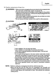
... shortened service life. * Use of controls or adjustments or performance of procedures other purposes. NOTE: * Perform cutting by overlapping the ink line with 21 CFR, Chapter 1, Subchapter J. If the switch trigger is pulledinadvertently,the saw blade can rotate and result in handling a switch ...receptacle during a cutting operation. Do not stare into beam. 43 Fig. 16 * Laser radiation- Position adjustment of lines. otherwise,the position of a laser line can be used for the position adjustment of tool); Do not stare into beam. If your eye is exposed directly to ...
... shortened service life. * Use of controls or adjustments or performance of procedures other purposes. NOTE: * Perform cutting by overlapping the ink line with 21 CFR, Chapter 1, Subchapter J. If the switch trigger is pulledinadvertently,the saw blade can rotate and result in handling a switch ...receptacle during a cutting operation. Do not stare into beam. 43 Fig. 16 * Laser radiation- Position adjustment of lines. otherwise,the position of a laser line can be used for the position adjustment of tool); Do not stare into beam. If your eye is exposed directly to ...
Instruction Manual
Page 22
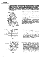
... become difficult to observe the laser line due to "13.G roove cutting procedures" on page 37. A switch lights up . The laser line is adjusted to the width of the saw blade, align the laser line with the left side of the cutting width (saw blade and the laser line taking the following steps... to the left.) When you turn it . Adjust the positions of factory shipment. Under such ...
... become difficult to observe the laser line due to "13.G roove cutting procedures" on page 37. A switch lights up . The laser line is adjusted to the width of the saw blade, align the laser line with the left side of the cutting width (saw blade and the laser line taking the following steps... to the left.) When you turn it . Adjust the positions of factory shipment. Under such ...
Instruction Manual
Page 23
... again and check the position of the laser line, draw a right-angle ink line on the workpiece and align the ink line with the laser line. NOTE: Check and make adjustments again following the steps from (1) to change the laser line's position, make sure on the ...C12LSH) (Also serves as laser marker power switch.) Fig. 22-a the laser marker. (On the C12RSH, only the laser marker switch.) 23 Left is .) Miter angle reset button RESET ItiCK UNIT RESET Bevel angle reset button Fig. 21 Back light ON/OFF switch (Press and the switch illuminates. When aligning the ink line, slide...
... again and check the position of the laser line, draw a right-angle ink line on the workpiece and align the ink line with the laser line. NOTE: Check and make adjustments again following the steps from (1) to change the laser line's position, make sure on the ...C12LSH) (Also serves as laser marker power switch.) Fig. 22-a the laser marker. (On the C12RSH, only the laser marker switch.) 23 Left is .) Miter angle reset button RESET ItiCK UNIT RESET Bevel angle reset button Fig. 21 Back light ON/OFF switch (Press and the switch illuminates. When aligning the ink line, slide...
Instruction Manual
Page 26
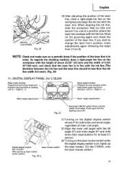
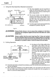
...laser line. (Front view) (2) Once the saw blade reaches Fig. 26 maximum speed, push the handle down carefully until the saw blade approaches the workpiece. (3) Once the saw blade contacts the workpiece, push the handle down gradually to return it will not contact the saw blade is desired. English 2. After the adjustment... vise to secure the workpiece to the full retract position. 26 Cutting Operation (1) As shown in position (Fig. 25). Therefore, slide the workpiece to the right (viewed from the table and cause bodily harm. &CAUTION: Always confirm that it may do so, ...
...laser line. (Front view) (2) Once the saw blade reaches Fig. 26 maximum speed, push the handle down carefully until the saw blade approaches the workpiece. (3) Once the saw blade contacts the workpiece, push the handle down gradually to return it will not contact the saw blade is desired. English 2. After the adjustment... vise to secure the workpiece to the full retract position. 26 Cutting Operation (1) As shown in position (Fig. 25). Therefore, slide the workpiece to the right (viewed from the table and cause bodily harm. &CAUTION: Always confirm that it may do so, ...

Parts List
Page 7
... 973-313 NYLON CLIP 1 193 305-180 CLUTCH SCREW 1 194 305-179 CLUTCH SPRING 1 195 962-614 ADJUSTING WASHER (B) T0.5 1 196 319-268 PLATE (B) 1 197 305-179 CLUTCH SPRING 1 198 321-348 LASER MARKER 1 199 319-267 SPRING 2 200 319-541 SEAL LOCK HEX. TAPPING SCREW D5X50 2 256 360-711U ARMATURE ASS...
... 973-313 NYLON CLIP 1 193 305-180 CLUTCH SCREW 1 194 305-179 CLUTCH SPRING 1 195 962-614 ADJUSTING WASHER (B) T0.5 1 196 319-268 PLATE (B) 1 197 305-179 CLUTCH SPRING 1 198 321-348 LASER MARKER 1 199 319-267 SPRING 2 200 319-541 SEAL LOCK HEX. TAPPING SCREW D5X50 2 256 360-711U ARMATURE ASS...


