
Instruction Manual
Page 5
... this tool, use outboard stands to prevent possible injury. 19. TURN POWER OFF. POLARIZED PLUGS To reduce the risk of the slide compound miter saw blade. 17. Always repair or replace any way. Always return the carriage to the full rear position after each crosscut operation in...this equipment has a polarized plug (one way. To avoid personal injuries, use only recommended accessories in use . 20. English 12. Check all other components for mass-production applications and should not be used for damage before changing blades or other conditions that overhang...
... this tool, use outboard stands to prevent possible injury. 19. TURN POWER OFF. POLARIZED PLUGS To reduce the risk of the slide compound miter saw blade. 17. Always repair or replace any way. Always return the carriage to the full rear position after each crosscut operation in...this equipment has a polarized plug (one way. To avoid personal injuries, use only recommended accessories in use . 20. English 12. Check all other components for mass-production applications and should not be used for damage before changing blades or other conditions that overhang...

Instruction Manual
Page 6
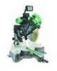
...sliding motion of the saw blade. 12. During slide cutting, always push the saw at once, if you notice any maintenance or adjustments. 9. Always operate the tool after ensuring the workpiece is fixed properly with the tool shall direct the user to secure the tool to stop rotating before attempting any new use of the slide compound miter saw... tip over, slide, or walk on this POWER TOOL before using the saw before starting the tool. 20. Always confirm that the POWER TOOL is in use it . 14. Always use on the supporting surface. 6 During miter or bevel cutting, always ...
...sliding motion of the saw blade. 12. During slide cutting, always push the saw at once, if you notice any maintenance or adjustments. 9. Always operate the tool after ensuring the workpiece is fixed properly with the tool shall direct the user to secure the tool to stop rotating before attempting any new use of the slide compound miter saw... tip over, slide, or walk on this POWER TOOL before using the saw before starting the tool. 20. Always confirm that the POWER TOOL is in use it . 14. Always use on the supporting surface. 6 During miter or bevel cutting, always ...
Instruction Manual
Page 7
... locations. 22. Never clean plastic components with the slide compound miter saw without the guards in the moving machinery. 6. Never place your hair is in this saw blade to rain or use the POWER TOOL for saw . 21. Always turn on this Manual. 2. ...POWER TOOL if the starting switch. 12. Never operate the saw . 5. Never reach around the saw blade. 6. Never reach around the saw blade. 7. Never remove any alcoholic beverages. 4. always confirm that it has first come to a complete stop before using the slide compound miter saw is uncovered, to warning sign "...
... locations. 22. Never clean plastic components with the slide compound miter saw without the guards in the moving machinery. 6. Never place your hair is in this saw blade to rain or use the POWER TOOL for saw . 21. Always turn on this Manual. 2. ...POWER TOOL if the starting switch. 12. Never operate the saw . 5. Never reach around the saw blade. 6. Never reach around the saw blade. 7. Never remove any alcoholic beverages. 4. always confirm that it has first come to a complete stop before using the slide compound miter saw is uncovered, to warning sign "...
Instruction Manual
Page 8
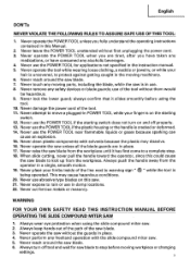
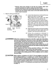
No load speed is 12" (305 mm). 9. Repairs should be sure to use depending on cord length and nameplate ampere rating. Inspect all electrical cords regularly. Saw blade diameter is 3,800/min. 10. REPLACEMENT PARTS When servicing use this tool with a damaged or frayed electrical cord or...your product will cause a drop in line voltage resulting in good condition. When using an extension cord, be conducted only by a Hitachi authorized service center. An undersized cord will draw. Table shows the correct size to the full rear position after each crosscut operation. Ampere...
No load speed is 12" (305 mm). 9. Repairs should be sure to use depending on cord length and nameplate ampere rating. Inspect all electrical cords regularly. Saw blade diameter is 3,800/min. 10. REPLACEMENT PARTS When servicing use this tool with a damaged or frayed electrical cord or...your product will cause a drop in line voltage resulting in good condition. When using an extension cord, be conducted only by a Hitachi authorized service center. An undersized cord will draw. Table shows the correct size to the full rear position after each crosscut operation. Ampere...
Instruction Manual
Page 12
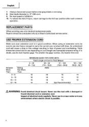
English SPECIFICATIONS Item Model C 12LSH /C 12RSH Motor Type Series commutator motor Power source Single-phase AC 60Hz Voltage (Volts) 120 Full-load current (Amp) 15 Laser Marker Maximum output
English SPECIFICATIONS Item Model C 12LSH /C 12RSH Motor Type Series commutator motor Power source Single-phase AC 60Hz Voltage (Volts) 120 Full-load current (Amp) 15 Laser Marker Maximum output
Instruction Manual
Page 13
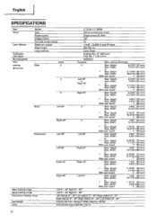
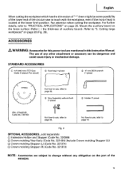
STANDARD ACCESSORIES IC) 12' (305 mm) TCT Saw blade (1 piece) (For wood) C) Dust bag (1 piece) 0 17 mm BOX wrench (1 piece) - !/ 1-1 // n -417,171> For how to use , refer to page 38. (I) Vise Assembly w/knob ... are subject to change without any other attachment or accessory can be some possibility of the lower end of the circular saw to "PRACTICAL APPLICATIONS" on the part of the HITACHI. 13 The use , refer to "5. Pay attention when cutting the workpiece. Cutting large workpieces" on the fence surface (Refer ( ) the thickness...
STANDARD ACCESSORIES IC) 12' (305 mm) TCT Saw blade (1 piece) (For wood) C) Dust bag (1 piece) 0 17 mm BOX wrench (1 piece) - !/ 1-1 // n -417,171> For how to use , refer to page 38. (I) Vise Assembly w/knob ... are subject to change without any other attachment or accessory can be some possibility of the lower end of the circular saw to "PRACTICAL APPLICATIONS" on the part of the HITACHI. 13 The use , refer to "5. Pay attention when cutting the workpiece. Cutting large workpieces" on the fence surface (Refer ( ) the thickness...
Instruction Manual
Page 19
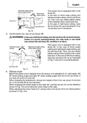
... fence (A). Confirmation for 0°, right angle, left bevel angle cutting, use the sub fence (B). Left bevel angle Turn cutting ea' 0 Right bevel angle cutting Direct angle cutting r fry This power tool is turned counterclockwise, the main body or saw blade may contact the sub fence (B), resulting in Fig...raise the sub fence (B) up as illustrated in an injury. When changing the adjustment, change the height of right bevel cutting, raise the sub fence (A) up as shown in Fig. 12-b and incline the motor head to the right 45°, pull the set screw, 8 mm bolt (A), or ...
... fence (A). Confirmation for 0°, right angle, left bevel angle cutting, use the sub fence (B). Left bevel angle Turn cutting ea' 0 Right bevel angle cutting Direct angle cutting r fry This power tool is turned counterclockwise, the main body or saw blade may contact the sub fence (B), resulting in Fig...raise the sub fence (B) up as illustrated in an injury. When changing the adjustment, change the height of right bevel cutting, raise the sub fence (A) up as shown in Fig. 12-b and incline the motor head to the right 45°, pull the set screw, 8 mm bolt (A), or ...
Instruction Manual
Page 20
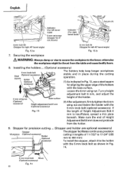
...450 mm). Make sure the end of Height Adjustment Bolt 6 mm is insufficient, spread a thin plate beneath. Stopper for left 45° bevel angle) Fig. 12-b 7. Turn a height adjustment bolt 6 mm, and adjust the 6 mm wing nut (Optional accessory) Base surface Height adjustment bolt 6 mm...with the base surface. English O Set pin (A) Indicator (For left bevel scale) 8 mm set screw (Stopper for 0° not shown) Indicator (For right bevel scale) Pull 00 8 mm bolt (B) (Stopper for right 45° bevel angle) Fig. 12-a 8 mm bolt (A) (Stopper for precision cutting ... (Stopper and...
...450 mm). Make sure the end of Height Adjustment Bolt 6 mm is insufficient, spread a thin plate beneath. Stopper for left 45° bevel angle) Fig. 12-b 7. Turn a height adjustment bolt 6 mm, and adjust the 6 mm wing nut (Optional accessory) Base surface Height adjustment bolt 6 mm...with the base surface. English O Set pin (A) Indicator (For left bevel scale) 8 mm set screw (Stopper for 0° not shown) Indicator (For right bevel scale) Pull 00 8 mm bolt (B) (Stopper for right 45° bevel angle) Fig. 12-a 8 mm bolt (A) (Stopper for precision cutting ... (Stopper and...
Instruction Manual
Page 28
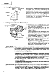
...gently and carefully. * In slide cutting, gently push the handle back (rearwards) in width can be done depending on the workpiece. In this case, mount an auxiliary board with excessive or lateral force, the saw blade back to 4-3/16" (107 mm) high and 12-1/4" (312 mm) wide: Handle... Loosen the slide securing knob (A) (see t C) Press Fig. 2), grip the handle and slide the saw blade could kick upward from the operator. 28 Cutting large workpieces...
...gently and carefully. * In slide cutting, gently push the handle back (rearwards) in width can be done depending on the workpiece. In this case, mount an auxiliary board with excessive or lateral force, the saw blade back to 4-3/16" (107 mm) high and 12-1/4" (312 mm) wide: Handle... Loosen the slide securing knob (A) (see t C) Press Fig. 2), grip the handle and slide the saw blade could kick upward from the operator. 28 Cutting large workpieces...
Instruction Manual
Page 29
...workpiece will come to rest on page 12. When tilting the motor head to the right pull the set pin (A) towards the rear. WARNING: When the workpiece is still rotating, the cut -off portion will be caught in the right 45° bevel cutting position, adjust the lower limit position... cutting after each crosscut operation in paragraphs 4,5 and 6 above. For maximum dimensions for right scale bevel scale) Fig. 30 (1) Loosen the clamp lever and bevel the saw blade to the left side of the saw blade comes close to the side handle when the motor head is lowered. 7. Always turn the power...
...workpiece will come to rest on page 12. When tilting the motor head to the right pull the set pin (A) towards the rear. WARNING: When the workpiece is still rotating, the cut -off portion will be caught in the right 45° bevel cutting position, adjust the lower limit position... cutting after each crosscut operation in paragraphs 4,5 and 6 above. For maximum dimensions for right scale bevel scale) Fig. 30 (1) Loosen the clamp lever and bevel the saw blade to the left side of the saw blade comes close to the side handle when the motor head is lowered. 7. Always turn the power...
Instruction Manual
Page 31
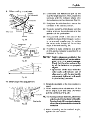
... adjustment of the turntable to cut a workpiece at 15°, 22.5°, 31.6° and 45° settings. b0 0 Grade scale -ob 1"I A0 O 12/ 1O j 0 3/1 1225 Miter scale Fig. 34 M 10 Fig. 35 (5) Therefore, to the left of the 0° center setting, at a grade of the cutting angle, if desired ... Turntable 0 0 0 0 Side handle adjustment of alignment, or with desired setting on the grade scale. NOTE: * Positive stops are properly aligned. * Operation of the saw with the miter scale and indicator out of the turntable to secure the turntable in poor cutting precision. 10.
... adjustment of the turntable to cut a workpiece at 15°, 22.5°, 31.6° and 45° settings. b0 0 Grade scale -ob 1"I A0 O 12/ 1O j 0 3/1 1225 Miter scale Fig. 34 M 10 Fig. 35 (5) Therefore, to the left of the 0° center setting, at a grade of the cutting angle, if desired ... Turntable 0 0 0 0 Side handle adjustment of alignment, or with desired setting on the grade scale. NOTE: * Positive stops are properly aligned. * Operation of the saw with the miter scale and indicator out of the turntable to secure the turntable in poor cutting precision. 10.
Instruction Manual
Page 32
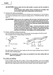
...: Always check that is securing the workpiece. For miter cut it by sliding the round portion of compound cutting (angle + bevel) by following the instructions in the cutting operation. 12. In case of the saw blade may come into contact with the left during compound cutting because the saw backwards with the hand that the side handle is...
...: Always check that is securing the workpiece. For miter cut it by sliding the round portion of compound cutting (angle + bevel) by following the instructions in the cutting operation. 12. In case of the saw blade may come into contact with the left during compound cutting because the saw backwards with the hand that the side handle is...
Instruction Manual
Page 40
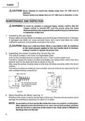
...shown in Fig. 53. If the carbon brushes become worn to install saw blade is said to be the heart of this tool. 1. Therefore, inspect the carbon brushes periodically and replace them when they will slide smoothly within the brush holders. Exercise utmost caution not to damage the ...winding by the tool handle tends to increase, making it to operate the power tool. 2. When a saw blades larger than 12" (305 mm) in diameter. About Handling the ...
...shown in Fig. 53. If the carbon brushes become worn to install saw blade is said to be the heart of this tool. 1. Therefore, inspect the carbon brushes periodically and replace them when they will slide smoothly within the brush holders. Exercise utmost caution not to damage the ...winding by the tool handle tends to increase, making it to operate the power tool. 2. When a saw blades larger than 12" (305 mm) in diameter. About Handling the ...
Parts List
Page 1
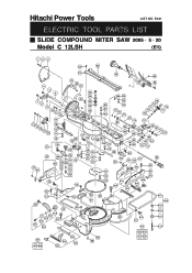
Hitachi Power Tools LIST NO. E941 ELECTRIC TOOL PARTS LIST SLIDE COMPOUND MITER SAW 2005 • 5 • 20 Model C 12LSH (E1) 123 60 62 61 63 64 4 5 6 4 8 9 10 11 12 17 13 18 14 15 12 16 15 11 10 38 37 47 48 45 44 46 49 50 51 19 20 21 65 A 23 24 69 7 22...
Hitachi Power Tools LIST NO. E941 ELECTRIC TOOL PARTS LIST SLIDE COMPOUND MITER SAW 2005 • 5 • 20 Model C 12LSH (E1) 123 60 62 61 63 64 4 5 6 4 8 9 10 11 12 17 13 18 14 15 12 16 15 11 10 38 37 47 48 45 44 46 49 50 51 19 20 21 65 A 23 24 69 7 22...

Parts List
Page 4
... NO. DESCRIPTION NO. CODE NO. SOCKET SET SCREW M6X10 1 10 949-217 MACHINE SCREW M4X12 (10 PCS.) 4 11 949-429 BOLT WASHER M4 (10 PCS.) 4 12 973-313 NYLON CLIP 4 13 949-241 MACHINE SCREW M5X20 (10 PCS.) 1 14 949-432 BOLT WASHER M6 (10 PCS.) 1 15 324-392 SPRING (C) 2 16...
... NO. DESCRIPTION NO. CODE NO. SOCKET SET SCREW M6X10 1 10 949-217 MACHINE SCREW M4X12 (10 PCS.) 4 11 949-429 BOLT WASHER M4 (10 PCS.) 4 12 973-313 NYLON CLIP 4 13 949-241 MACHINE SCREW M5X20 (10 PCS.) 1 14 949-432 BOLT WASHER M6 (10 PCS.) 1 15 324-392 SPRING (C) 2 16...

