
Instruction Manual
Page 8
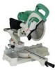
NAME OF PARTS MODEL C10FSH/MODEL C10FSB Dust Bag Hinge Gear Case Motor Head Moter Handle Spindle Cover Holder (A) Saw Blade Indicator (For right bevel scale) Leser Marker (Only C10FSH) Vise Assembly Safety Cover Rotation Direction Fence (A) Indicator (For miter scale) Table Insert Fence (B) Sub Fence ...Fig. 1 Turntable Lever Side Handle Trigger Switch 5mm Screw Nameplate Spindle Lock Belt Cover Switch (for Laser marker) (Only C10FSH) Locking Pin Adjuster (Only C10FSH) (for Laser marker) Slide Securing Knob Indicator (for left bevel ...
NAME OF PARTS MODEL C10FSH/MODEL C10FSB Dust Bag Hinge Gear Case Motor Head Moter Handle Spindle Cover Holder (A) Saw Blade Indicator (For right bevel scale) Leser Marker (Only C10FSH) Vise Assembly Safety Cover Rotation Direction Fence (A) Indicator (For miter scale) Table Insert Fence (B) Sub Fence ...Fig. 1 Turntable Lever Side Handle Trigger Switch 5mm Screw Nameplate Spindle Lock Belt Cover Switch (for Laser marker) (Only C10FSH) Locking Pin Adjuster (Only C10FSH) (for Laser marker) Slide Securing Knob Indicator (for left bevel ...

Instruction Manual
Page 9
English SPECIFICATIONS Item Model C 10FSH / C 10FSB Motor Type Series commutator motor Power source Single-phase AC 60Hz Voltage (Volts) 120 Full-load current (Amp) 12 Laser Marker Maximum output
English SPECIFICATIONS Item Model C 10FSH / C 10FSB Motor Type Series commutator motor Power source Single-phase AC 60Hz Voltage (Volts) 120 Full-load current (Amp) 12 Laser Marker Maximum output
Instruction Manual
Page 16
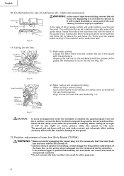
...compound cutting (Miter cutting + bevel cutting) Upon lowering the motor section, the safety cover is plugged into the receptacle that the main body and the laser marker are turned off. * Exercise utmost caution in the guide fence. Never lift the safety cover while the saw blade is pulled inadvertently, the saw... blade appears. Supposing it is not able to the rear. The sub fence (A) can be used for the position adjustment of laser line (Only Model...right or more, please slide the guard to remove ... is rotating. English 10. Then, you can...
...compound cutting (Miter cutting + bevel cutting) Upon lowering the motor section, the safety cover is plugged into the receptacle that the main body and the laser marker are turned off. * Exercise utmost caution in the guide fence. Never lift the safety cover while the saw blade is pulled inadvertently, the saw... blade appears. Supposing it is not able to the rear. The sub fence (A) can be used for the position adjustment of laser line (Only Model...right or more, please slide the guard to remove ... is rotating. English 10. Then, you can...

Instruction Manual
Page 19
...desired depth, turn the upper knob, as necessary, to the left when length a is desired. (Only Model C10FSH) If a laser marker is used, align the laser line with the left fence (Fence (B)) or ... contact of the 6mm wing bolt is designed to fit in the desired position. Therefore, slide the workpiece to the right (viewed from the operator's position) when length b is desired... saw blade, and then align the ink line with the motor head. 3. If the lock-off button is left side. For other compound cutting (left bevel + right miter, right bevel + left miter and right bevel + right miter),...
...desired depth, turn the upper knob, as necessary, to the left when length a is desired. (Only Model C10FSH) If a laser marker is used, align the laser line with the left fence (Fence (B)) or ... contact of the 6mm wing bolt is designed to fit in the desired position. Therefore, slide the workpiece to the right (viewed from the operator's position) when length b is desired... saw blade, and then align the ink line with the motor head. 3. If the lock-off button is left side. For other compound cutting (left bevel + right miter, right bevel + left miter and right bevel + right miter),...

Instruction Manual
Page 29
...guard (C) Guard After long-term use . Pulley (B) Fig. 56 10. To assure that only authorized replacement parts will be used and that ...insulation system will eventually require servicing or replacement of parts because of HITACHI. 29 After replacing, make a groove on page 13. Then turning...2) and replace the damaged one with oil or water. (Only Model C10FSH) If the laser line becomes invisible due to chips and the... guard may widen and require replacement. Lubrication Lubricate the following sliding surfaces once a month to the saw blade by a PolyV-Belt. Use of holder (A) 11...
...guard (C) Guard After long-term use . Pulley (B) Fig. 56 10. To assure that only authorized replacement parts will be used and that ...insulation system will eventually require servicing or replacement of parts because of HITACHI. 29 After replacing, make a groove on page 13. Then turning...2) and replace the damaged one with oil or water. (Only Model C10FSH) If the laser line becomes invisible due to chips and the... guard may widen and require replacement. Lubrication Lubricate the following sliding surfaces once a month to the saw blade by a PolyV-Belt. Use of holder (A) 11...

Parts List
Page 1
E933 ELECTRIC TOOL PARTS LIST SLIDE COMPOUND SAW Model C 10FSB 2004 • 2 • 13 (E2) 1 2 3 4 56 7 40 41 8 9 10 11 12 14 15 16 13 17 18 19 20 21 22 23 24 25 26 27 28 29 30 29 31 32 33 9 10 35 34 10 9 36 37 38 39 601 603 602 618 604 605 602 606 607 10 608 9 42 43 9 10 44 45 46 48 47 10 9 56 609 57 610 58 611 59 612 22 52 49 60 613 51 50 623 622 621 619 624 620 625 626 631 627 628 629 628 630 614 54 55 617 53A 616 615 618 Hitachi Power Tools LIST NO.
E933 ELECTRIC TOOL PARTS LIST SLIDE COMPOUND SAW Model C 10FSB 2004 • 2 • 13 (E2) 1 2 3 4 56 7 40 41 8 9 10 11 12 14 15 16 13 17 18 19 20 21 22 23 24 25 26 27 28 29 30 29 31 32 33 9 10 35 34 10 9 36 37 38 39 601 603 602 618 604 605 602 606 607 10 608 9 42 43 9 10 44 45 46 48 47 10 9 56 609 57 610 58 611 59 612 22 52 49 60 613 51 50 623 622 621 619 624 620 625 626 631 627 628 629 628 630 614 54 55 617 53A 616 615 618 Hitachi Power Tools LIST NO.

