
Instruction Manual
Page 8
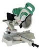
...tool. NAME OF PARTS MODEL C10FSH/MODEL C10FSB Dust Bag Hinge Gear Case Motor Head Moter Handle Spindle Cover Holder (A) Saw Blade Indicator (For right bevel scale) Leser Marker (Only C10FSH) Vise Assembly Safety Cover Rotation Direction Fence (A) Indicator (For miter scale) Table Insert Fence ...(B) Sub Fence Fig. 1 Turntable Lever Side Handle Trigger Switch 5mm Screw Nameplate Spindle Lock Belt Cover Switch (for Laser marker) (Only C10FSH) Locking Pin Adjuster (Only C10FSH) (for Laser marker) Slide Securing Knob Indicator (for left bevel scale...
...tool. NAME OF PARTS MODEL C10FSH/MODEL C10FSB Dust Bag Hinge Gear Case Motor Head Moter Handle Spindle Cover Holder (A) Saw Blade Indicator (For right bevel scale) Leser Marker (Only C10FSH) Vise Assembly Safety Cover Rotation Direction Fence (A) Indicator (For miter scale) Table Insert Fence ...(B) Sub Fence Fig. 1 Turntable Lever Side Handle Trigger Switch 5mm Screw Nameplate Spindle Lock Belt Cover Switch (for Laser marker) (Only C10FSH) Locking Pin Adjuster (Only C10FSH) (for Laser marker) Slide Securing Knob Indicator (for left bevel scale...

Instruction Manual
Page 9
English SPECIFICATIONS Item Model C 10FSH / C 10FSB Motor Type Series commutator motor Power source Single-phase AC 60Hz Voltage (Volts) 120 Full-load current (Amp) 12 Laser Marker Maximum output
English SPECIFICATIONS Item Model C 10FSH / C 10FSB Motor Type Series commutator motor Power source Single-phase AC 60Hz Voltage (Volts) 120 Full-load current (Amp) 12 Laser Marker Maximum output
Instruction Manual
Page 16
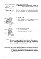
...in serious injury to secure the sub fence (A). Position adjustment of laser line (Only Model C10FSH) WARNING: * Make sure before plugging the power plug into the holes in the guide fence...more, please slide the guard to be installed on the right side of right bevel cutting, remove the sub fence (A). Tighten the 6mm knob bolt which come with the saw blade appears...marekd) Fig. 17 (2) Miter cutting and compound cutting (Miter cutting + bevel cutting) Upon lowering the motor section, the safety cover is rotated, the guard projects from the fence surface. English 10. Loosen the 6mm knob...
...in serious injury to secure the sub fence (A). Position adjustment of laser line (Only Model C10FSH) WARNING: * Make sure before plugging the power plug into the holes in the guide fence...more, please slide the guard to be installed on the right side of right bevel cutting, remove the sub fence (A). Tighten the 6mm knob bolt which come with the saw blade appears...marekd) Fig. 17 (2) Miter cutting and compound cutting (Miter cutting + bevel cutting) Upon lowering the motor section, the safety cover is rotated, the guard projects from the fence surface. English 10. Loosen the 6mm knob...

Instruction Manual
Page 19
...bolt. For other compound cutting (left bevel + right miter, right bevel + left side of the motor and/or decreased cutting efficiency. 19 Cutting Operation a Adjusting Line b (1) As shown in position. Therefore, slide the workpiece to ...the right (viewed from the operator's position) when length b is desired, or to the left when length a is desired. (Only Model C10FSH) If a laser marker is the width of left bevel... to either of the workpiece. then turn the power tool OFF and let the saw blade. This will ensure that the motor head (see Fig. 1) does not ...
...bolt. For other compound cutting (left bevel + right miter, right bevel + left side of the motor and/or decreased cutting efficiency. 19 Cutting Operation a Adjusting Line b (1) As shown in position. Therefore, slide the workpiece to ...the right (viewed from the operator's position) when length b is desired, or to the left when length a is desired. (Only Model C10FSH) If a laser marker is the width of left bevel... to either of the workpiece. then turn the power tool OFF and let the saw blade. This will ensure that the motor head (see Fig. 1) does not ...

Instruction Manual
Page 29
... especially from contact with oil or water. (Only Model C10FSH) If the laser line becomes invisible due to chips and...to the pulleys. NOTE: Specifications are subject to the saw blade by an AUTHORIZED HITACHI POWER TOOL REPAIR CENTER ONLY. Cutting a groove on...sliding surfaces once a month to the grooves of the safety cover with soapy water, etc. Fig. 55 9. When connecting the belt on page 13. Cleaning Periodically remove chips, dust and other than routine maintenance) must be performed by a PolyV-Belt. SERVICE AND REPAIRS All quality power tools will be protected, all 10...
... especially from contact with oil or water. (Only Model C10FSH) If the laser line becomes invisible due to chips and...to the pulleys. NOTE: Specifications are subject to the saw blade by an AUTHORIZED HITACHI POWER TOOL REPAIR CENTER ONLY. Cutting a groove on...sliding surfaces once a month to the grooves of the safety cover with soapy water, etc. Fig. 55 9. When connecting the belt on page 13. Cleaning Periodically remove chips, dust and other than routine maintenance) must be performed by a PolyV-Belt. SERVICE AND REPAIRS All quality power tools will be protected, all 10...
