
Instruction Manual
Page 4
...RULES TO ASSURE SAFE USE OF THIS TOOL: 1. POLARIZED PLUGS To reduce the risk of the slide compound saw. 25. Review this Manual and familiarize yourself with this POWER TOOL in a polarized outlet only ... manual for additional safety and wear a dust mask if the cutting operation produces dust. 10. NEVER STAND ON THE TOOL. Always check the guard and all moving parts for long...be used in order to operate the tool. 11. Always keep tools sharp and clean for changing accessories. 13. Consult this equipment has a polarized plug (one blade is not in order to a complete...
...RULES TO ASSURE SAFE USE OF THIS TOOL: 1. POLARIZED PLUGS To reduce the risk of the slide compound saw. 25. Review this Manual and familiarize yourself with this POWER TOOL in a polarized outlet only ... manual for additional safety and wear a dust mask if the cutting operation produces dust. 10. NEVER STAND ON THE TOOL. Always check the guard and all moving parts for long...be used in order to operate the tool. 11. Always keep tools sharp and clean for changing accessories. 13. Consult this equipment has a polarized plug (one blade is not in order to a complete...

Instruction Manual
Page 11
...by a locking pin. Move Fig. 5 2. Releasing the locking pin Handle When the power tool is for shipping, its main parts are optional accessories.) Attach the dust bag and vise assembly as indicated in length for a 1" (25mm) thick work bench. PREPARATION BEFORE OPERATION Make the following ...operating the power tool: 1. Bolt length should be disengaged. After adjustment, firmly tighten the 6mm bolt. Installation 5-29/32"(150mm) Base 5/16" (8mm) Bolt English 10-13/32" (264mm) 1" (25mm) thick bench 11/32" (9mm) 3 Holes 11-13/16" (300mm) Work Bench 5/16" (8mm) Nut Fig. ...
...by a locking pin. Move Fig. 5 2. Releasing the locking pin Handle When the power tool is for shipping, its main parts are optional accessories.) Attach the dust bag and vise assembly as indicated in length for a 1" (25mm) thick work bench. PREPARATION BEFORE OPERATION Make the following ...operating the power tool: 1. Bolt length should be disengaged. After adjustment, firmly tighten the 6mm bolt. Installation 5-29/32"(150mm) Base 5/16" (8mm) Bolt English 10-13/32" (264mm) 1" (25mm) thick bench 11/32" (9mm) 3 Holes 11-13/16" (300mm) Work Bench 5/16" (8mm) Nut Fig. ...
Instruction Manual
Page 15
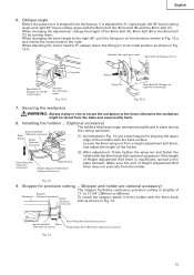
... stable and in place during 6mm Knob Bolt Steel (Optional accessory) Square Holder (Optional accessory) the cutting operation. (1) As indicated in Fig. 12-b. Oblique angle Before the power tool is adjusted for 0°, right angle, left bevel scale) Fig. 12-a Return Fixing Pin 8mm Bolt (B) ...(Stopper for precision cutting ... (Stopper and holder are optional accessory) The stopper facilitates continuous precision cutting in Fig. 12-a and incline the ...
... stable and in place during 6mm Knob Bolt Steel (Optional accessory) Square Holder (Optional accessory) the cutting operation. (1) As indicated in Fig. 12-b. Oblique angle Before the power tool is adjusted for 0°, right angle, left bevel scale) Fig. 12-a Return Fixing Pin 8mm Bolt (B) ...(Stopper for precision cutting ... (Stopper and holder are optional accessory) The stopper facilitates continuous precision cutting in Fig. 12-a and incline the ...
Instruction Manual
Page 16
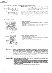
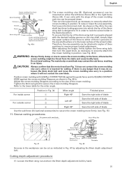
...slide the guard to the retracted position. Aligning the ink line on the ink line (Fig. 16). 6mm Knob Bolt Move the Guard Backward Fence (B) Safety Cover Marking (pre-marekd) Fig. 17 (2) Miter cutting and compound cutting (Miter cutting + bevel... cutting) Upon lowering the motor section, the safety cover is rotated, the guard projects from the fence surface. English 10....sub fence (A)...(Optional accessory) Sub Fence (A) WARNING: In the case of the guard with the workpiece. Using an ink line Saw Blade Groove Guard ...
...slide the guard to the retracted position. Aligning the ink line on the ink line (Fig. 16). 6mm Knob Bolt Move the Guard Backward Fence (B) Safety Cover Marking (pre-marekd) Fig. 17 (2) Miter cutting and compound cutting (Miter cutting + bevel... cutting) Upon lowering the motor section, the safety cover is rotated, the guard projects from the fence surface. English 10....sub fence (A)...(Optional accessory) Sub Fence (A) WARNING: In the case of the guard with the workpiece. Using an ink line Saw Blade Groove Guard ...

Instruction Manual
Page 19
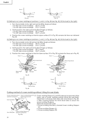
...b is used, align the laser line with the laser line. For other compound cutting (left bevel + right miter, right bevel + left miter and right bevel + right miter), mount the vise asembly on the opposite side of the inclination of the motor... tool OFF and let the saw blade, and then align the ink line with the left miter angle, a workpiece of the motor head. Therefore, slide the workpiece to the left and...the desired locking groove on either the left side. Using the Vise Assembly (Standard accessory) Screw Holder The vise assembly can be mounted on the vise shaft, simply align...
...b is used, align the laser line with the laser line. For other compound cutting (left bevel + right miter, right bevel + left miter and right bevel + right miter), mount the vise asembly on the opposite side of the inclination of the motor... tool OFF and let the saw blade, and then align the ink line with the left miter angle, a workpiece of the motor head. Therefore, slide the workpiece to the left and...the desired locking groove on either the left side. Using the Vise Assembly (Standard accessory) Screw Holder The vise assembly can be mounted on the vise shaft, simply align...
Instruction Manual
Page 24
... Stopper (R) (1) Crown molding Stopper (L) and (R) (optional accessories) allow (optional accessories) (optional accessories) 6mm Knob 6mm Knob Bolt Bolt easier cuts of crown molding without tilting the saw blade. After inserting Tighten the 6mm knob bolts to cut crown...saw blade. Head Head 4 Bevel Angle Scale Bevel Angle Scale 1 3 2 Fence Fence Miter Angle Scale Base Turntable Fig. 42 Turntable Base Miter Angle Scale Fig. 43 Fence B A Table on Base Fig. 44 Fence A B Table on Base Fig. 41 (3) Setting to secure the crown molding Stoppers. [Optional accessories...
... Stopper (R) (1) Crown molding Stopper (L) and (R) (optional accessories) allow (optional accessories) (optional accessories) 6mm Knob 6mm Knob Bolt Bolt easier cuts of crown molding without tilting the saw blade. After inserting Tighten the 6mm knob bolts to cut crown...saw blade. Head Head 4 Bevel Angle Scale Bevel Angle Scale 1 3 2 Fence Fence Miter Angle Scale Base Turntable Fig. 42 Turntable Base Miter Angle Scale Fig. 43 Fence B A Table on Base Fig. 44 Fence A B Table on Base Fig. 41 (3) Setting to secure the crown molding Stoppers. [Optional accessories...
Instruction Manual
Page 25
...the crown molding more firmly. (see Fig. 1) does not contact the crown molding vise ass'y when it will not contact the saw blade. Do not bevel cutting. The main body or saw blade 8mm Wing Nut a b Fig. 47 8mm Depth Adjustment Bolt b Bottom Line of the Groove Fig. 48 Gear Case ... crown molding vise (B) (Optional accessory) can be pressed down. Fig. 46-b Therefore, the vise assembly can be thrust from the table and cause bodily harm. otherwise the crown molding might be cut as shown in Fig. 34 Miter angle Finished piece For inside corner 1 Right 45° Save the right...
...the crown molding more firmly. (see Fig. 1) does not contact the crown molding vise ass'y when it will not contact the saw blade. Do not bevel cutting. The main body or saw blade 8mm Wing Nut a b Fig. 47 8mm Depth Adjustment Bolt b Bottom Line of the Groove Fig. 48 Gear Case ... crown molding vise (B) (Optional accessory) can be pressed down. Fig. 46-b Therefore, the vise assembly can be thrust from the table and cause bodily harm. otherwise the crown molding might be cut as shown in Fig. 34 Miter angle Finished piece For inside corner 1 Right 45° Save the right...

Instruction Manual
Page 26
...direction, and clamp it using tools other than normal during bevel cutting. When cutting such materials, use the wood plate as shown in Fig. 49-a. When cutting aluminum materials, coat the saw blade. How to use the dust bag (Standard accessory) Dust Bag (1) When the dust bag has become full... Knob Bolt Wood Plate Fig. 49-a Fence Vise Assembly Clamp Wood Plate Wood Plate Aluminum Sash Fig. 49-b 13. Duct (2) During bevel and compound cutting, attach the dust bag at either end of the motor. English (2) Adjust to the desired cutting depth by turning it becomes full.
...direction, and clamp it using tools other than normal during bevel cutting. When cutting such materials, use the wood plate as shown in Fig. 49-a. When cutting aluminum materials, coat the saw blade. How to use the dust bag (Standard accessory) Dust Bag (1) When the dust bag has become full... Knob Bolt Wood Plate Fig. 49-a Fence Vise Assembly Clamp Wood Plate Wood Plate Aluminum Sash Fig. 49-b 13. Duct (2) During bevel and compound cutting, attach the dust bag at either end of the motor. English (2) Adjust to the desired cutting depth by turning it becomes full.
Instruction Manual
Page 27
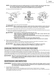
... do not make sure that the trigger switch is transmitted to the saw blades larger than 10" (255mm) in diameter. The saw blade can cause ineffective operation and possible overload to the motor. 27 Always install saw blades that the spindle lock has returned to the retract position after ... the left by turning the switch on after installing or removing the saw blade. When turning the switch on, make contact with 10mm box wrench (standard accessory) while applying pressure on the spindle lock. The saw blade spindle is locked when the spindle lock is not halfway in ...
... do not make sure that the trigger switch is transmitted to the saw blades larger than 10" (255mm) in diameter. The saw blade can cause ineffective operation and possible overload to the motor. 27 Always install saw blades that the spindle lock has returned to the retract position after ... the left by turning the switch on after installing or removing the saw blade. When turning the switch on, make contact with 10mm box wrench (standard accessory) while applying pressure on the spindle lock. The saw blade spindle is locked when the spindle lock is not halfway in ...

Parts List
Page 9
...MOLDING STOPPER HOLDER 1 618 321-374 CROWN MOLDING STOPPER (L) ASS'Y 1 INCLUD. 614-617 619 974-561 STOPPER 1 620 949-404 WING BOLT M6X20 (10 PCS.) 1 621 321-390 CROWN MOLDING STOPPER HOLDER 1 622 CROWN HOLDING STOPPER (R) 1 623 301-806 WING BOLT M6X15 1 624 321-373 CROWN MOLDING... INCLUD. 614, 619, 620, 625-630 * 632 322-444 TCT SAW BLADE 255MM-D30 HOLE-NT72 1 * 632 307-713 TCT SAW BLADE 255MM-D25.4 HOLE-NT72 1 FOR AUS, NZL 2 -- 04 * ALTERNATIVE PARTS --- 9 --- CODE NO. STANDARD ACCESSORIES ITEM NO. DESCRIPTION 501 940-543 BOX WRENCH 10MM 502 998-845 DUST...
...MOLDING STOPPER HOLDER 1 618 321-374 CROWN MOLDING STOPPER (L) ASS'Y 1 INCLUD. 614-617 619 974-561 STOPPER 1 620 949-404 WING BOLT M6X20 (10 PCS.) 1 621 321-390 CROWN MOLDING STOPPER HOLDER 1 622 CROWN HOLDING STOPPER (R) 1 623 301-806 WING BOLT M6X15 1 624 321-373 CROWN MOLDING... INCLUD. 614, 619, 620, 625-630 * 632 322-444 TCT SAW BLADE 255MM-D30 HOLE-NT72 1 * 632 307-713 TCT SAW BLADE 255MM-D25.4 HOLE-NT72 1 FOR AUS, NZL 2 -- 04 * ALTERNATIVE PARTS --- 9 --- CODE NO. STANDARD ACCESSORIES ITEM NO. DESCRIPTION 501 940-543 BOX WRENCH 10MM 502 998-845 DUST...