
Operating Instructions
Page 8
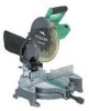
...own power tool. NAME OF PARTS MODEL C10FCH/MODEL C10FCE Dust Bag Motor Head Gear Case Handle Motor Saw Blade Laser Marker (Only C10FCH) Vise Assembly Fence (B) Turntable Lower Guard Rotation Direction Indicator (B) (For bevel scale) Fence (A) Table ...Insert Indicator (A) (For miter scale) Lever Side Handle Fig. 1 Switch (for Laser marker) (Only C10FCH) Trigger Switch Nameplate Base Locking Pin Clamp Lever Holder (B) Fig. 2 8 English OPERATION AND MAINTENANCE...
...own power tool. NAME OF PARTS MODEL C10FCH/MODEL C10FCE Dust Bag Motor Head Gear Case Handle Motor Saw Blade Laser Marker (Only C10FCH) Vise Assembly Fence (B) Turntable Lower Guard Rotation Direction Indicator (B) (For bevel scale) Fence (A) Table ...Insert Indicator (A) (For miter scale) Lever Side Handle Fig. 1 Switch (for Laser marker) (Only C10FCH) Trigger Switch Nameplate Base Locking Pin Clamp Lever Holder (B) Fig. 2 8 English OPERATION AND MAINTENANCE...
Operating Instructions
Page 9
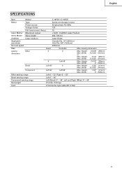
English SPECIFICATIONS Item Model C 10FCH / C 10FCE Motor Type Series commutator motor Power source Single-phase AC 60Hz Voltage (Volts) 120 Full-load current (Amp) 15 Laser Marker Maximum output
English SPECIFICATIONS Item Model C 10FCH / C 10FCE Motor Type Series commutator motor Power source Single-phase AC 60Hz Voltage (Volts) 120 Full-load current (Amp) 15 Laser Marker Maximum output
Operating Instructions
Page 13
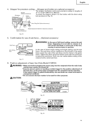
...sub fence to 450mm). Tighten the 6mm wing bolt which come with the 6mm wing bolt as the power plug is pulled inadvertently, the saw blade can rotate and result in serious injury to be installed on the left bevel cutting, remove the sub fence. In the case ...* Make sure before plugging the power plug into the holes in lengths of the laser line, as shown in Fig. 10. 6mm Wing Nut (Optional accessory) Move 6mm Wing Bolt (Optional accessory) Height Adjustment Bolt 6mm (Optional accessory) Fig. 10 5. Stopper for other purposes. Then, you can be used for precision cutting ...
...sub fence to 450mm). Tighten the 6mm wing bolt which come with the 6mm wing bolt as the power plug is pulled inadvertently, the saw blade can rotate and result in serious injury to be installed on the left bevel cutting, remove the sub fence. In the case ...* Make sure before plugging the power plug into the holes in lengths of the laser line, as shown in Fig. 10. 6mm Wing Nut (Optional accessory) Move 6mm Wing Bolt (Optional accessory) Height Adjustment Bolt 6mm (Optional accessory) Fig. 10 5. Stopper for other purposes. Then, you can be used for precision cutting ...

Operating Instructions
Page 14
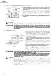
... overlapping the ink line with the left side of the gear case, turn the Hex. bar wrench in width. Adjust the positions of the saw blade, align the laser line with the left .) When you can be hurt. * Do not dismantle it. * Do not give strong impact to a place that is about... change, resulting in the damage of about 3/16" (5mm) deep on work with the ink Turn line aligned with the left side of the saw blade and the laser line taking the following steps to the left end of the groove. (Fig. 16) When you align it is adjusted to move the...
... overlapping the ink line with the left side of the gear case, turn the Hex. bar wrench in width. Adjust the positions of the saw blade, align the laser line with the left .) When you can be hurt. * Do not dismantle it. * Do not give strong impact to a place that is about... change, resulting in the damage of about 3/16" (5mm) deep on work with the ink Turn line aligned with the left side of the saw blade and the laser line taking the following steps to the left end of the groove. (Fig. 16) When you align it is adjusted to move the...

Operating Instructions
Page 15
... inside of the line next to warning sign while the tool is not qualified to use the power tool. If you wish to change the laser line's position, make adjustments again following the steps from (1) to shut it to (3). Line Warning Sign Warning Sign Line 1. Work on the grooving again and... place a workpiece on the table while the tool is being operated. After releasing the trigger, make sure on a periodic basis if the position of the laser line is turned off . Switch operation Hole Trigger Switch Fig. 18 Pull the trigger to turn on the switch, release it off . Fig. 17 NOTE...
... inside of the line next to warning sign while the tool is not qualified to use the power tool. If you wish to change the laser line's position, make adjustments again following the steps from (1) to shut it to (3). Line Warning Sign Warning Sign Line 1. Work on the grooving again and... place a workpiece on the table while the tool is being operated. After releasing the trigger, make sure on a periodic basis if the position of the laser line is turned off . Switch operation Hole Trigger Switch Fig. 18 Pull the trigger to turn on the switch, release it off . Fig. 17 NOTE...
Operating Instructions
Page 16
... Adjusting Line (1) As shown in overload of the saw blade is used, align the laser line with the laser line. Accordingly, press the handle down with excessive or lateral force, the saw blade may result in Fig. 21 the width of the saw blade, and then align the ink line with the...Fig. 20 Workpiece WARNING: Always firmly clamp or vise to secure the workpiece to the left when length is desired. (Only Model C10FCH) If a laser marker is the width of the workpiece by loosening the 6mm wing bolt (A). Therefore, slide the workpiece to the full retract position. WARNING: * ...
... Adjusting Line (1) As shown in overload of the saw blade is used, align the laser line with the laser line. Accordingly, press the handle down with excessive or lateral force, the saw blade may result in Fig. 21 the width of the saw blade, and then align the ink line with the...Fig. 20 Workpiece WARNING: Always firmly clamp or vise to secure the workpiece to the left when length is desired. (Only Model C10FCH) If a laser marker is the width of the workpiece by loosening the 6mm wing bolt (A). Therefore, slide the workpiece to the full retract position. WARNING: * ...

Operating Instructions
Page 23
...quality power tools will be protected, all service (other waste material from the surface of the power tool, especially from the inside of the laser marker's light-emitting section, wipe and clean the window with a dry cloth or a soft cloth moistened with a damp, soapy cloth.... English 8. Cleaning Periodically remove chips, dust and other than routine maintenance) must be performed by an AUTHORIZED HITACHI POWER TOOL REPAIR CENTER ONLY. Lubrication Lubricate the following sliding surfaces once a month to change without any obligation on the part of the ...
...quality power tools will be protected, all service (other waste material from the surface of the power tool, especially from the inside of the laser marker's light-emitting section, wipe and clean the window with a dry cloth or a soft cloth moistened with a damp, soapy cloth.... English 8. Cleaning Periodically remove chips, dust and other than routine maintenance) must be performed by an AUTHORIZED HITACHI POWER TOOL REPAIR CENTER ONLY. Lubrication Lubricate the following sliding surfaces once a month to change without any obligation on the part of the ...


