
Maintenance and Service Guide
Page 5
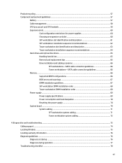
...System board architecture ...8 Workstation specifications ...9 Tower workstation components ...9 Front panel components ...11 Rear panel components ...12 Chassis components ...13 System board components ...14 System board architecture ...16 Workstation specifications ...17 Environmental ...specifications ...17 Ensuring proper ventilation ...19 2 System management ...20 Power management and performance features 20 ERP compliance mode ...20 Hyper-Threading Technology (HTT 21 SATA Power Management ...21 Intel Turbo Boost Technology ...21 HP...
...System board architecture ...8 Workstation specifications ...9 Tower workstation components ...9 Front panel components ...11 Rear panel components ...12 Chassis components ...13 System board components ...14 System board architecture ...16 Workstation specifications ...17 Environmental ...specifications ...17 Ensuring proper ventilation ...19 2 System management ...20 Power management and performance features 20 ERP compliance mode ...20 Hyper-Threading Technology (HTT 21 SATA Power Management ...21 Intel Turbo Boost Technology ...21 HP...
Maintenance and Service Guide
Page 7
... power supplies 60 Choosing an expansion card slot 60 SFF workstation slot identification and description 61 SFF workstation installation sequence recommendations 62 Tower workstation slot identification and description 63 Tower workstation installation sequence recommendations 64 Hard drives and optical disc drives...consumption and heat dissipation 70 Resetting the power supply 70 System board ...70 System cabling ...71 SFF workstation system cabling 71 Tower workstation system cabling 72 4 Diagnostics and troubleshooting ...73 Calling support ...74 Locating ID labels ...75 Locating ...
... power supplies 60 Choosing an expansion card slot 60 SFF workstation slot identification and description 61 SFF workstation installation sequence recommendations 62 Tower workstation slot identification and description 63 Tower workstation installation sequence recommendations 64 Hard drives and optical disc drives...consumption and heat dissipation 70 Resetting the power supply 70 System board ...70 System cabling ...71 SFF workstation system cabling 71 Tower workstation system cabling 72 4 Diagnostics and troubleshooting ...73 Calling support ...74 Locating ID labels ...75 Locating ...

Maintenance and Service Guide
Page 9
Appendix B Configuring RAID devices ...108 RAID hard drive maximum and associated storage controller options 109 Supported RAID configurations ...109 Configuring Intel SATA RAID ...110 Configuring system BIOS ...110 Configuring RAID with the Intel utility 111 Software RAID solution ...112 Software RAID considerations ...112 Performance considerations ...112 Configuring software RAID ...112 Appendix C System board designators ...114 SFF workstation system board designators ...114 Tower workstation system board designators 115 Index ...117 ix
Appendix B Configuring RAID devices ...108 RAID hard drive maximum and associated storage controller options 109 Supported RAID configurations ...109 Configuring Intel SATA RAID ...110 Configuring system BIOS ...110 Configuring RAID with the Intel utility 111 Software RAID solution ...112 Software RAID considerations ...112 Performance considerations ...112 Configuring software RAID ...112 Appendix C System board designators ...114 SFF workstation system board designators ...114 Tower workstation system board designators 115 Index ...117 ix

Maintenance and Service Guide
Page 11
1 Hardware overview This chapter presents an overview of workstation hardware components. Topics Small form factor workstation components on page 2 Tower workstation components on page 9 Environmental specifications on page 17 Ensuring proper ventilation on page 19 1
1 Hardware overview This chapter presents an overview of workstation hardware components. Topics Small form factor workstation components on page 2 Tower workstation components on page 9 Environmental specifications on page 17 Ensuring proper ventilation on page 19 1

Maintenance and Service Guide
Page 19
NOTE: To drive more displays, HP recommends using only discrete graphics cards). ● RAID configurations for SATA RAID levels 0, 1 ● Supports eSATA (3.0 Gbps...; 1600 MHz 2, 4, 8 GB non ECC unbuffered DIMM Supports: ● PCIe Gen3 (PCIe3) bus speeds; Tower workstation components 9 can be used with an optional PCI bulkhead connector Tower workstation components For complete and current information on processor type) ● Up to six 2D displays or four 3D displays ... channels enable low-latency access and fast data transfer for the computer, go to http://partsurfer.hp.com.
NOTE: To drive more displays, HP recommends using only discrete graphics cards). ● RAID configurations for SATA RAID levels 0, 1 ● Supports eSATA (3.0 Gbps...; 1600 MHz 2, 4, 8 GB non ECC unbuffered DIMM Supports: ● PCIe Gen3 (PCIe3) bus speeds; Tower workstation components 9 can be used with an optional PCI bulkhead connector Tower workstation components For complete and current information on processor type) ● Up to six 2D displays or four 3D displays ... channels enable low-latency access and fast data transfer for the computer, go to http://partsurfer.hp.com.

Maintenance and Service Guide
Page 21
Front panel components 1 Optical drive 6 USB 2.0 (Always-On Charging) port (1) 2 Second optical drive or optional component 7 USB 2.0 port (1) 3 Slim optical drive 8 USB 3.0 ports (2) 4 Hard drive or optical drive activity light 9 Headphone connector 5 Power button 10` Microphone connector Tower workstation components 11
Front panel components 1 Optical drive 6 USB 2.0 (Always-On Charging) port (1) 2 Second optical drive or optional component 7 USB 2.0 port (1) 3 Slim optical drive 8 USB 3.0 ports (2) 4 Hard drive or optical drive activity light 9 Headphone connector 5 Power button 10` Microphone connector Tower workstation components 11

Maintenance and Service Guide
Page 23
Item Description 1 Side access panel 2 Power supply 3 Chassis 4 Optical drive 5 Optional media reader or second hard drive Item Description 6 Slim optical drive 7 Front bezel 8 Hard drive (HDD) 9 Solid-state drive (SSD) 10 System board Tower workstation components 13 Drive configurations can vary. Chassis components The following figure shows the chassis components of a typical tower workstation layout.
Item Description 1 Side access panel 2 Power supply 3 Chassis 4 Optical drive 5 Optional media reader or second hard drive Item Description 6 Slim optical drive 7 Front bezel 8 Hard drive (HDD) 9 Solid-state drive (SSD) 10 System board Tower workstation components 13 Drive configurations can vary. Chassis components The following figure shows the chassis components of a typical tower workstation layout.

Maintenance and Service Guide
Page 24
I/O 1 Dual-Mode DisplayPort 2 Single-Link DVI-I 3 Front audio 4 Front speaker 5 Front USB 2.0 6 Front USB 3.0 7 Internal USB 2.0 14 Chapter 1 Hardware overview SATA 15 AHCI 6Gb/s PCI/PCIe 16 PCIe2 x4 (1) 17 PCIe3 x16 18 PCIe2 x1 19 PCIe2 x16 (4) Power 24 Battery 25 Processor 26 Front power button/LED 27 Main power Security 28 Chassis solenoid lock 29 Hood sensor System board components The following illustration and table identify the system board components for the tower workstation.
I/O 1 Dual-Mode DisplayPort 2 Single-Link DVI-I 3 Front audio 4 Front speaker 5 Front USB 2.0 6 Front USB 3.0 7 Internal USB 2.0 14 Chapter 1 Hardware overview SATA 15 AHCI 6Gb/s PCI/PCIe 16 PCIe2 x4 (1) 17 PCIe3 x16 18 PCIe2 x1 19 PCIe2 x16 (4) Power 24 Battery 25 Processor 26 Front power button/LED 27 Main power Security 28 Chassis solenoid lock 29 Hood sensor System board components The following illustration and table identify the system board components for the tower workstation.

Maintenance and Service Guide
Page 25
8 Internal USB 3.0 9 Keyboard / mouse 10 Network / rear USB 2.0 11 Parallel (optional) 12 Rear audio 13 Rear USB 2.0/3.0 14 Serial (optional) 20 PCI 32/33 NOTE: For related expansion card slot information, see Expansion slots on page 60 Cooling 21 Processor fan 22 Front fan (option) 23 Rear fan Service 30 Clear CMOS button 31 Crisis recovery jumper 32 ME/AMT flash override 33 Password jumper Tower workstation components 15
8 Internal USB 3.0 9 Keyboard / mouse 10 Network / rear USB 2.0 11 Parallel (optional) 12 Rear audio 13 Rear USB 2.0/3.0 14 Serial (optional) 20 PCI 32/33 NOTE: For related expansion card slot information, see Expansion slots on page 60 Cooling 21 Processor fan 22 Front fan (option) 23 Rear fan Service 30 Clear CMOS button 31 Crisis recovery jumper 32 ME/AMT flash override 33 Password jumper Tower workstation components 15

Maintenance and Service Guide
Page 73
..., so a PCIe x16 card can be inserted. Component replacement guidelines 63 Slot four is the secondary graphics slot. slot two is the primary graphics slot; Tower workstation slot identification and description Maximum power used by all slots must not exceed total system power and is mechanically a x16 length connector, with 4 PCIe2 lanes...
..., so a PCIe x16 card can be inserted. Component replacement guidelines 63 Slot four is the secondary graphics slot. slot two is the primary graphics slot; Tower workstation slot identification and description Maximum power used by all slots must not exceed total system power and is mechanically a x16 length connector, with 4 PCIe2 lanes...

Maintenance and Service Guide
Page 74
Slot 4 Only Slot 5 2nd 1st 1st 3rd 64 Chapter 3 Component replacement information and guidelines Tower workstation installation sequence recommendations Load order Card description Slot 1 Slot 2 Slot 3 1 PCIe graphic card 2 Second PCIe graphic card Only 3 PCIe NIC card 3rd 1st 4 PCIe 1394 card 2nd 3rd 5 PCIe audio card 2nd 3rd 6 eSATA bulkhead kit 1st 2nd 7 Parallel port kit Only 8 Second serial port kit 1st 2nd NOTE: Slot sequenced from the board edge to the rear I/O aperture.
Slot 4 Only Slot 5 2nd 1st 1st 3rd 64 Chapter 3 Component replacement information and guidelines Tower workstation installation sequence recommendations Load order Card description Slot 1 Slot 2 Slot 3 1 PCIe graphic card 2 Second PCIe graphic card Only 3 PCIe NIC card 3rd 1st 4 PCIe 1394 card 2nd 3rd 5 PCIe audio card 2nd 3rd 6 eSATA bulkhead kit 1st 2nd 7 Parallel port kit Only 8 Second serial port kit 1st 2nd NOTE: Slot sequenced from the board edge to the rear I/O aperture.

Maintenance and Service Guide
Page 76
...x1 ODD x1 HDD x2 ODD x1 SATA 0 1st HDD 1st HDD SATA 1 1st ODD 2nd HDD SATA 2 1st ODD SATA 5 e-SATA e-SATA Tower workstations-SATA cable connection guidelines Configuration / PCA SATA connector HDD x1 ODD x1 HDD x1 ODD x2 HDD x2 ODD x1 HDD x2 ODD x2 HDD... section presents cabling guidelines for highest drive performance and efficient cable routing. If you add or remove drives, HP recommends you follow these guidelines for the most common maximum storage configurations. Platform SFF Tower ● Four DIMM slots ● Unbuffered ECC/nECC DIMMS only ● Maximum capacity: 32 GB ●...
...x1 ODD x1 HDD x2 ODD x1 SATA 0 1st HDD 1st HDD SATA 1 1st ODD 2nd HDD SATA 2 1st ODD SATA 5 e-SATA e-SATA Tower workstations-SATA cable connection guidelines Configuration / PCA SATA connector HDD x1 ODD x1 HDD x1 ODD x2 HDD x2 ODD x1 HDD x2 ODD x2 HDD... section presents cabling guidelines for highest drive performance and efficient cable routing. If you add or remove drives, HP recommends you follow these guidelines for the most common maximum storage configurations. Platform SFF Tower ● Four DIMM slots ● Unbuffered ECC/nECC DIMMS only ● Maximum capacity: 32 GB ●...

Maintenance and Service Guide
Page 78
NOTE: If you install DIMMs of different sizes, load them in order of size, starting with largest and finishing with the smallest (largest in DIMM 1, smallest in last loaded DIMM). 68 Chapter 3 Component replacement information and guidelines SFF workstation DIMM installation order Install DIMMs in this order. Tower workstation DIMM installation order Install DIMMs in this order. NOTE: If you install DIMMs of different sizes, load them in order of size, starting with largest and finishing with the smallest (largest in DIMM 1, smallest in last loaded DIMM).
NOTE: If you install DIMMs of different sizes, load them in order of size, starting with largest and finishing with the smallest (largest in DIMM 1, smallest in last loaded DIMM). 68 Chapter 3 Component replacement information and guidelines SFF workstation DIMM installation order Install DIMMs in this order. Tower workstation DIMM installation order Install DIMMs in this order. NOTE: If you install DIMMs of different sizes, load them in order of size, starting with largest and finishing with the smallest (largest in DIMM 1, smallest in last loaded DIMM).

Maintenance and Service Guide
Page 82
... SATA cable First ODD eSATA bracket cable (optional) First external SATA device Cable designator on page 14 to determine the location of system board connectors. Tower workstation system cabling See System board components on system board P1 (White) P3 (White) P8 (Black) P9 (Black) P10 (Black) P12 (Black) P13 (White) P14 (Black...
... SATA cable First ODD eSATA bracket cable (optional) First external SATA device Cable designator on page 14 to determine the location of system board connectors. Tower workstation system cabling See System board components on system board P1 (White) P3 (White) P8 (Black) P9 (Black) P10 (Black) P12 (Black) P13 (White) P14 (Black...

Maintenance and Service Guide
Page 125
Designator P160 XBT1 XMM1 - DIMM4 XU1 Component/Description HDD power (black) Battery holder Memory slots CPU socket Tower workstation system board designators Designator E15 E49 J9 J10 J31 J33 J34 J41 J42 J64 J65 J68 J83 J86 MTG1-MTG10 P1 P3 P5 P6 P8 ... sensor/Temperature header Speaker CPU fan header Front fan header Rear system fan Front audio header Front panel USB header Front panel USB3 header (blue) Tower workstation system board designators 115 XMM4 XU1 Silk screen SATAPWR1 XBT1 BAT XMM1 - XMM4 DIMM1 -
Designator P160 XBT1 XMM1 - DIMM4 XU1 Component/Description HDD power (black) Battery holder Memory slots CPU socket Tower workstation system board designators Designator E15 E49 J9 J10 J31 J33 J34 J41 J42 J64 J65 J68 J83 J86 MTG1-MTG10 P1 P3 P5 P6 P8 ... sensor/Temperature header Speaker CPU fan header Front fan header Rear system fan Front audio header Front panel USB header Front panel USB3 header (blue) Tower workstation system board designators 115 XMM4 XU1 Silk screen SATAPWR1 XBT1 BAT XMM1 - XMM4 DIMM1 -

Maintenance and Service Guide
Page 127
... and troubleshooting Diagnosis guidelines 76 Locating ID labels 75 Locating warranty info 76 DIMM configurations, supported 66 DIMM installation order SFF workstation 68 Tower workstation 68 E Expansion card slot identification SFF Workstation 61 Tower Workstation 63 H HP PC Hardware Diagnostics (UEFI) downloading 91 using 91 M Memory DIMM installation guidelines 67 O Operating system setup 104 P Password configuration 100...
... and troubleshooting Diagnosis guidelines 76 Locating ID labels 75 Locating warranty info 76 DIMM configurations, supported 66 DIMM installation order SFF workstation 68 Tower workstation 68 E Expansion card slot identification SFF Workstation 61 Tower Workstation 63 H HP PC Hardware Diagnostics (UEFI) downloading 91 using 91 M Memory DIMM installation guidelines 67 O Operating system setup 104 P Password configuration 100...

Z228 Workstation Maintenance and Service Guide
Page 13
Chassis components The following figure shows the chassis components of a typical tower workstation layout. Drive configurations can vary. Item Description 1 Solid-state drive (SSD) 2 Hard drive (HDD) 3 Side access panel 4 Front bezel 5 Heat sink fan 6 Power supply Item Description 7 System board 8 System fan 9 Memory module 10 Slim optical drive 11 Chassis Workstation components 3
Chassis components The following figure shows the chassis components of a typical tower workstation layout. Drive configurations can vary. Item Description 1 Solid-state drive (SSD) 2 Hard drive (HDD) 3 Side access panel 4 Front bezel 5 Heat sink fan 6 Power supply Item Description 7 System board 8 System fan 9 Memory module 10 Slim optical drive 11 Chassis Workstation components 3

Z228 Workstation Maintenance and Service Guide
Page 14
... ME/AMT flash override 32 Password jumper 4 Chapter 1 Hardware overview System board components The following illustration and table identify the system board components for the tower workstation.
... ME/AMT flash override 32 Password jumper 4 Chapter 1 Hardware overview System board components The following illustration and table identify the system board components for the tower workstation.

User Guide
Page 5
Table of contents 1 Locating HP resources ...1 Product information ...2 Support ...3 Product documentation ...4 Product diagnostics ...4 Product updates ...5 2 Workstation features ...6 Small form factor workstation components 7 Front panel ...7 Rear panel ...8 Tower workstation components ...8 Font panel ...8 Rear panel ...10 Product specifications ...10 Workstation weights and dimensions 10 Environmental specifications 11 3 Setting up the workstation ...12 Ensuring proper ventilation ...13 Setup procedures ...14 Adding...
Table of contents 1 Locating HP resources ...1 Product information ...2 Support ...3 Product documentation ...4 Product diagnostics ...4 Product updates ...5 2 Workstation features ...6 Small form factor workstation components 7 Front panel ...7 Rear panel ...8 Tower workstation components ...8 Font panel ...8 Rear panel ...10 Product specifications ...10 Workstation weights and dimensions 10 Environmental specifications 11 3 Setting up the workstation ...12 Ensuring proper ventilation ...13 Setup procedures ...14 Adding...

User Guide
Page 14
2 Workstation features For complete and current information about supported accessories and components for your workstation, see http://partsurfer.hp.com. Topics Small form factor workstation components on page 7 Tower workstation components on page 8 Product specifications on page 10 6 Chapter 2 Workstation features
2 Workstation features For complete and current information about supported accessories and components for your workstation, see http://partsurfer.hp.com. Topics Small form factor workstation components on page 7 Tower workstation components on page 8 Product specifications on page 10 6 Chapter 2 Workstation features


