Memory Modules
Page 3
... components. Memory Modules 1-1 The primary memory module compartment is located on the bottom of the computer. The expansion memory module compartment is located under the keyboard. 1 Adding or replacing memory modules The computer has 2 memory module compartments.
... components. Memory Modules 1-1 The primary memory module compartment is located on the bottom of the computer. The expansion memory module compartment is located under the keyboard. 1 Adding or replacing memory modules The computer has 2 memory module compartments.
Memory Modules
Page 11
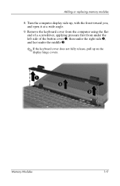
Memory Modules 1-9 Remove the keyboard cover from the computer using the flat end of a screwdriver, applying pressure first from under the left side of the button cover 1, then under the right side 2, and last under the middle 3. ✎ If the keyboard cover does not fully release, pull up , with the front toward you, and open it at a wide angle. 9. Turn the computer display-side up on the display hinge covers. Adding or replacing memory modules 8.
Memory Modules 1-9 Remove the keyboard cover from the computer using the flat end of a screwdriver, applying pressure first from under the left side of the button cover 1, then under the right side 2, and last under the middle 3. ✎ If the keyboard cover does not fully release, pull up , with the front toward you, and open it at a wide angle. 9. Turn the computer display-side up on the display hinge covers. Adding or replacing memory modules 8.
Memory Modules
Page 12
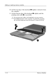
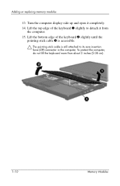
To protect the computer, do not lift the keyboard more than about 2 inches (5.08 cm). 1-10 Memory Modules Lift the top edge of the keyboard 2 slightly until the pointing stick cable 3 is accessible. Ä The pointing stick cable is still attached to detach it from the computer. 11. Lift the bottom edge of the keyboard 1 slightly to its zero insertion force (ZIF) connector in the computer. Adding or replacing memory modules 10.
To protect the computer, do not lift the keyboard more than about 2 inches (5.08 cm). 1-10 Memory Modules Lift the top edge of the keyboard 2 slightly until the pointing stick cable 3 is accessible. Ä The pointing stick cable is still attached to detach it from the computer. 11. Lift the bottom edge of the keyboard 1 slightly to its zero insertion force (ZIF) connector in the computer. Adding or replacing memory modules 10.

Memory Modules
Page 14
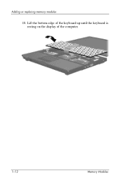
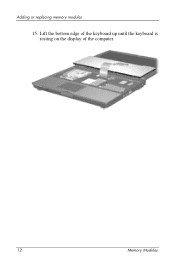
Lift the bottom edge of the keyboard up until the keyboard is resting on the display of the computer. 1-12 Memory Modules Adding or replacing memory modules 14.
Lift the bottom edge of the keyboard up until the keyboard is resting on the display of the computer. 1-12 Memory Modules Adding or replacing memory modules 14.
Memory Modules
Page 18
Turn the computer upside down on the computer by reversing the steps for removing the cover. 21. To protect the computer, be sure to replace the screws into the locations noted during removal. 23. Replace the keyboard cover on a flat surface. 22. Turn on the bottom of the computer are of the computer. Ä The screws on the computer. 1-16 Memory Modules Replace the keyboard. 20. Replace the battery pack(s). 24. Replace the screws on the bottom of different lengths. Reconnect external power and external devices. 25. Adding or replacing memory modules 19.
Turn the computer upside down on the computer by reversing the steps for removing the cover. 21. To protect the computer, be sure to replace the screws into the locations noted during removal. 23. Replace the keyboard cover on a flat surface. 22. Turn on the bottom of the computer are of the computer. Ä The screws on the computer. 1-16 Memory Modules Replace the keyboard. 20. Replace the battery pack(s). 24. Replace the screws on the bottom of different lengths. Reconnect external power and external devices. 25. Adding or replacing memory modules 19.

Memory Modules
Page 3
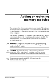
1 Adding or replacing memory modules The computer has 2 memory module compartments. The memory capacity of the computer can be upgraded by adding a memory module to the equipment, unplug ... illustrations in the primary memory module slot. Å WARNING: To reduce the risk of the computer. The expansion memory module compartment is located under the keyboard. Before beginning any procedure, ensure that you are discharged of static electricity by upgrading the existing memory module in this chapter. Memory Modules 1-1
1 Adding or replacing memory modules The computer has 2 memory module compartments. The memory capacity of the computer can be upgraded by adding a memory module to the equipment, unplug ... illustrations in the primary memory module slot. Å WARNING: To reduce the risk of the computer. The expansion memory module compartment is located under the keyboard. Before beginning any procedure, ensure that you are discharged of static electricity by upgrading the existing memory module in this chapter. Memory Modules 1-1

Memory Modules
Page 10
Tilt the keyboard cover up from the front edge 3 to release the rear edge of the cover from the computer. 11. Turn the computer display-side up the right rear corner edge 1 and then the left rear corner edge 2 of the keyboard cover to release the front edge of the cover from the computer. 1-8 Memory Modules Adding or replacing memory modules 9. Lift up , with the front toward you and open it. 10.
Tilt the keyboard cover up from the front edge 3 to release the rear edge of the cover from the computer. 11. Turn the computer display-side up the right rear corner edge 1 and then the left rear corner edge 2 of the keyboard cover to release the front edge of the cover from the computer. 1-8 Memory Modules Adding or replacing memory modules 9. Lift up , with the front toward you and open it. 10.

Memory Modules
Page 11
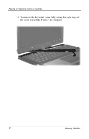
Memory Modules 1-9 To remove the keyboard cover fully, swing the right edge of the cover toward the front of the computer. Adding or replacing memory modules 12.
Memory Modules 1-9 To remove the keyboard cover fully, swing the right edge of the cover toward the front of the computer. Adding or replacing memory modules 12.
Memory Modules
Page 12
Lift the top edge of the keyboard 2 slightly until the pointing stick cable 3 is accessible. Ä The pointing stick cable is still attached to detach it completely. 14. To protect the computer, do not lift the keyboard more than about 2 inches (5.08 cm). 1-10 Memory Modules Lift the bottom edge of the keyboard 1 slightly to its zero insertion force (ZIF) connector in the computer. Turn the computer display-side up and open it from the computer. 15. Adding or replacing memory modules 13.
Lift the top edge of the keyboard 2 slightly until the pointing stick cable 3 is accessible. Ä The pointing stick cable is still attached to detach it completely. 14. To protect the computer, do not lift the keyboard more than about 2 inches (5.08 cm). 1-10 Memory Modules Lift the bottom edge of the keyboard 1 slightly to its zero insertion force (ZIF) connector in the computer. Turn the computer display-side up and open it from the computer. 15. Adding or replacing memory modules 13.
Memory Modules
Page 14
Lift the bottom edge of the keyboard up until the keyboard is resting on the display of the computer. 1-12 Memory Modules Adding or replacing memory modules 18.
Lift the bottom edge of the keyboard up until the keyboard is resting on the display of the computer. 1-12 Memory Modules Adding or replacing memory modules 18.
Memory Modules
Page 18
...different lengths. Reconnect external power and external devices. 30. Replace the keyboard. 24. Turn the computer upside down on the bottom of the computer are of the computer. Ä The screws on a flat surface. 26. Replace the base enclosure cover. 27. Press along the front edge...25. Adding or replacing memory modules 23. Replace the battery pack(s). 29. Turn on the computer by reversing the steps for removing the cover. (Reseat the left side of the keyboard cover to replace the screws in the locations noted during removal. 28. Replace the keyboard cover on the computer...
...different lengths. Reconnect external power and external devices. 30. Replace the keyboard. 24. Turn the computer upside down on the bottom of the computer are of the computer. Ä The screws on a flat surface. 26. Replace the base enclosure cover. 27. Press along the front edge...25. Adding or replacing memory modules 23. Replace the battery pack(s). 29. Turn on the computer by reversing the steps for removing the cover. (Reseat the left side of the keyboard cover to replace the screws in the locations noted during removal. 28. Replace the keyboard cover on the computer...
Memory Modules - Windows Vista
Page 3
Adding or replacing memory modules The computer has 2 memory module compartments. Memory Modules 1 The expansion memory module compartment is located under the keyboard. Before beginning any procedure, ensure that you are discharged of the computer. The memory capacity of the computer can damage electronic components. The primary memory ...
Adding or replacing memory modules The computer has 2 memory module compartments. Memory Modules 1 The expansion memory module compartment is located under the keyboard. Before beginning any procedure, ensure that you are discharged of the computer. The memory capacity of the computer can damage electronic components. The primary memory ...

Memory Modules - Windows Vista
Page 11
Memory Modules 9 Turn the computer display-side up on the display hinge covers. Adding or replacing memory modules 9. Remove the keyboard cover from the computer using the flat end of a screwdriver, applying pressure first from under the left side of the button cover 1, then under the right side 2, and last under the middle 3. ✎ If the keyboard cover does not fully release, pull up , with the front toward you, and open it at a wide angle. 10.
Memory Modules 9 Turn the computer display-side up on the display hinge covers. Adding or replacing memory modules 9. Remove the keyboard cover from the computer using the flat end of a screwdriver, applying pressure first from under the left side of the button cover 1, then under the right side 2, and last under the middle 3. ✎ If the keyboard cover does not fully release, pull up , with the front toward you, and open it at a wide angle. 10.

Memory Modules - Windows Vista
Page 12
Adding or replacing memory modules 11. Lift the top edge of the keyboard 2 slightly until the pointing stick cable 3 is accessible. Ä The pointing stick cable is still attached to detach it from the computer. 12. To protect the computer, do not lift the keyboard more than about 2 inches (5.08 cm). 10 Memory Modules Lift the bottom edge of the keyboard 1 slightly to its zero insertion force (ZIF) connector in the computer.
Adding or replacing memory modules 11. Lift the top edge of the keyboard 2 slightly until the pointing stick cable 3 is accessible. Ä The pointing stick cable is still attached to detach it from the computer. 12. To protect the computer, do not lift the keyboard more than about 2 inches (5.08 cm). 10 Memory Modules Lift the bottom edge of the keyboard 1 slightly to its zero insertion force (ZIF) connector in the computer.
Memory Modules - Windows Vista
Page 14
Adding or replacing memory modules 15. Lift the bottom edge of the keyboard up until the keyboard is resting on the display of the computer. 12 Memory Modules
Adding or replacing memory modules 15. Lift the bottom edge of the keyboard up until the keyboard is resting on the display of the computer. 12 Memory Modules
Memory Modules - Windows Vista
Page 18
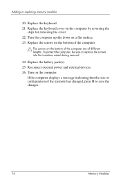
Replace the keyboard cover on a flat surface. 23. Reconnect external power and external devices. 26. If the computer displays a message indicating that the size or configuration of the memory has changed, press f1 to replace the screws into the locations noted during removal. 24. Turn the ...the steps for removing the cover. 22. Replace the battery pack(s). 25. To protect the computer, be sure to save the changes. 16 Memory Modules Replace the keyboard. 21. Replace the screws on the bottom of different lengths. Adding or replacing memory modules 20. Turn on the bottom ...
Replace the keyboard cover on a flat surface. 23. Reconnect external power and external devices. 26. If the computer displays a message indicating that the size or configuration of the memory has changed, press f1 to replace the screws into the locations noted during removal. 24. Turn the ...the steps for removing the cover. 22. Replace the battery pack(s). 25. To protect the computer, be sure to save the changes. 16 Memory Modules Replace the keyboard. 21. Replace the screws on the bottom of different lengths. Adding or replacing memory modules 20. Turn on the bottom ...

Memory Modules - Windows Vista
Page 3
...the primary memory module slot. Å WARNING: To reduce the risk of the computer. Memory Modules 1 The expansion memory module compartment is located under the keyboard. Before beginning any procedure, ensure that you are discharged of static electricity by adding a memory module to the equipment, unplug the power cord and remove... all battery packs before installing a memory module. Ä CAUTION: Electrostatic discharge (ESD) can damage electronic components. Adding or replacing memory modules The computer has 2 memory module compartments.
...the primary memory module slot. Å WARNING: To reduce the risk of the computer. Memory Modules 1 The expansion memory module compartment is located under the keyboard. Before beginning any procedure, ensure that you are discharged of static electricity by adding a memory module to the equipment, unplug the power cord and remove... all battery packs before installing a memory module. Ä CAUTION: Electrostatic discharge (ESD) can damage electronic components. Adding or replacing memory modules The computer has 2 memory module compartments.

Memory Modules - Windows Vista
Page 11
Lift up the right rear corner edge 1 and then the left rear corner edge 2 of the keyboard cover to release the front edge of the cover from the computer. Turn the computer display-side up from the front edge 3 to release the rear edge of the cover from the computer. 12. Memory Modules 9 Adding or replacing memory modules 10. Tilt the keyboard cover up , with the front toward you and open it. 11.
Lift up the right rear corner edge 1 and then the left rear corner edge 2 of the keyboard cover to release the front edge of the cover from the computer. Turn the computer display-side up from the front edge 3 to release the rear edge of the cover from the computer. 12. Memory Modules 9 Adding or replacing memory modules 10. Tilt the keyboard cover up , with the front toward you and open it. 11.
Memory Modules - Windows Vista
Page 12
To remove the keyboard cover fully, swing the right edge of the cover toward the front of the computer. 10 Memory Modules Adding or replacing memory modules 13.
To remove the keyboard cover fully, swing the right edge of the cover toward the front of the computer. 10 Memory Modules Adding or replacing memory modules 13.

Memory Modules - Windows Vista
Page 13
Lift the top edge of the keyboard 2 slightly until the pointing stick cable 3 is accessible. Ä The pointing stick cable is still attached to detach it completely. 15. Lift the bottom edge of the keyboard 1 slightly to its zero insertion force (ZIF) connector in the computer. To protect the computer, do not lift the keyboard more than about 2 inches (5.08 cm). Memory Modules 11 Turn the computer display-side up and open it from the computer. 16. Adding or replacing memory modules 14.
Lift the top edge of the keyboard 2 slightly until the pointing stick cable 3 is accessible. Ä The pointing stick cable is still attached to detach it completely. 15. Lift the bottom edge of the keyboard 1 slightly to its zero insertion force (ZIF) connector in the computer. To protect the computer, do not lift the keyboard more than about 2 inches (5.08 cm). Memory Modules 11 Turn the computer display-side up and open it from the computer. 16. Adding or replacing memory modules 14.


