Computer Setup - Windows Vista and Windows XP
Page 9
... exit Save changes and exit To do this ● View identification information for the processor, cache and memory size, system ROM, video revision, and keyboard controller version. Replace the configuration settings in the system. ● View specification information for the computer and the batteries in Computer Setup with the original factory settings...
... exit Save changes and exit To do this ● View identification information for the processor, cache and memory size, system ROM, video revision, and keyboard controller version. Replace the configuration settings in the system. ● View specification information for the computer and the batteries in Computer Setup with the original factory settings...

Drives - Linux
Page 20
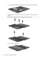
Remove the screws from the system board by pulling upward. 16 Chapter 4 Replacing the hard drive NOTE: Refer to be removed. Release the ZIF connector (1) to which the keyboard cable is accessible. 13. Slide the keyboard (1) towards the display assembly, and then turn the keyboard upside down (2) so that most closely matches your computer. 12. 11. Your computer has either 2 or 3 screws that need to the illustration that the keyboard cable is attached, and then disconnect the keyboard cable (2) from the keyboard.
Remove the screws from the system board by pulling upward. 16 Chapter 4 Replacing the hard drive NOTE: Refer to be removed. Release the ZIF connector (1) to which the keyboard cable is accessible. 13. Slide the keyboard (1) towards the display assembly, and then turn the keyboard upside down (2) so that most closely matches your computer. 12. 11. Your computer has either 2 or 3 screws that need to the illustration that the keyboard cable is attached, and then disconnect the keyboard cable (2) from the keyboard.

Drives - Linux
Page 25
6. Your computer has either 2 or 3 screws that most closely matches your computer. 7. Place the keyboard upside down on the system board. 21 Replace the screws to be installed. Insert the keyboard cable (2) into the ZIF connector (3) on the top cover of the computer (1). 8. NOTE: Refer to the illustration that need to the top cover.
6. Your computer has either 2 or 3 screws that most closely matches your computer. 7. Place the keyboard upside down on the system board. 21 Replace the screws to be installed. Insert the keyboard cable (2) into the ZIF connector (3) on the top cover of the computer (1). 8. NOTE: Refer to the illustration that need to the top cover.
Drives - Linux
Page 26
9. Your computer has either 2 or 3 screws that most closely matches your computer. 11. NOTE: Refer to the illustration that need to be replaced. Replace the screws on the keyboard. Slide the switch cover into place. 10. Turn over the keyboard (1) into the keyboard tray, and then slide the keyboard (2) into place. 22 Chapter 4 Replacing the hard drive
9. Your computer has either 2 or 3 screws that most closely matches your computer. 11. NOTE: Refer to the illustration that need to be replaced. Replace the screws on the keyboard. Slide the switch cover into place. 10. Turn over the keyboard (1) into the keyboard tray, and then slide the keyboard (2) into place. 22 Chapter 4 Replacing the hard drive

Drives - Linux
Page 29
...-Layer LightScribe Drive 3 C CD copying or creating 8 playing 6 removing 9 CD drive 2, 11 copyright warning 7 H hard disk drive external 11 installing 19 replacing 13 hard drive external 11 installing 19 replacing 13 K keyboard removing 16 O optical disc removing 9 using 4 optical drive 2, 11 D diskette drive 11 drives caring for 1 diskette 11 DVD+/-RW SuperMulti Double...
...-Layer LightScribe Drive 3 C CD copying or creating 8 playing 6 removing 9 CD drive 2, 11 copyright warning 7 H hard disk drive external 11 installing 19 replacing 13 hard drive external 11 installing 19 replacing 13 K keyboard removing 16 O optical disc removing 9 using 4 optical drive 2, 11 D diskette drive 11 drives caring for 1 diskette 11 DVD+/-RW SuperMulti Double...

Drives - Windows Vista
Page 26
Remove the screws from the system board by pulling upward. 22 Chapter 6 Replacing the hard drive Your computer has either 2 or 3 screws that need to the illustration that the keyboard cable is attached, and then disconnect the keyboard cable (2) from the keyboard. Slide the keyboard (1) towards the display assembly, and then turn the keyboard upside down (2) so that most closely matches your computer. 12. NOTE: Refer to be removed. Release the ZIF connector (1) to which the keyboard cable is accessible. 13. 11.
Remove the screws from the system board by pulling upward. 22 Chapter 6 Replacing the hard drive Your computer has either 2 or 3 screws that need to the illustration that the keyboard cable is attached, and then disconnect the keyboard cable (2) from the keyboard. Slide the keyboard (1) towards the display assembly, and then turn the keyboard upside down (2) so that most closely matches your computer. 12. NOTE: Refer to be removed. Release the ZIF connector (1) to which the keyboard cable is accessible. 13. 11.

Drives - Windows Vista
Page 31
6. Place the keyboard upside down on the system board. 27 NOTE: Refer to be installed. Your computer has either 2 or 3 screws that need to the illustration that most closely matches your computer. 7. Replace the screws to the top cover. Insert the keyboard cable (2) into the ZIF connector (3) on the top cover of the computer (1). 8.
6. Place the keyboard upside down on the system board. 27 NOTE: Refer to be installed. Your computer has either 2 or 3 screws that need to the illustration that most closely matches your computer. 7. Replace the screws to the top cover. Insert the keyboard cable (2) into the ZIF connector (3) on the top cover of the computer (1). 8.

Drives - Windows Vista
Page 32
Slide the switch cover into place. 10. NOTE: Refer to the illustration that need to be replaced. Turn over the keyboard (1) into the keyboard tray, and then slide the keyboard (2) into place. 28 Chapter 6 Replacing the hard drive Replace the screws on the keyboard. 9. Your computer has either 2 or 3 screws that most closely matches your computer. 11.
Slide the switch cover into place. 10. NOTE: Refer to the illustration that need to be replaced. Turn over the keyboard (1) into the keyboard tray, and then slide the keyboard (2) into place. 28 Chapter 6 Replacing the hard drive Replace the screws on the keyboard. 9. Your computer has either 2 or 3 screws that most closely matches your computer. 11.
Drives - Windows Vista
Page 44
...-Layer LightScribe Drive 3 C CD burning 11 copying 10 playing 6 removing 12 CD drive 2, 13 copyright warning 9 D device drivers HP 37 Microsoft 37 reinstalling 37 Disk Cleanup software 18 Disk Defragmenter software 18 disk performance 18 diskette drive 13 drive light 16 drives caring for... region codes, DVD 8 E external drive 13 H hard disk drive external 13 HP 3D DriveGuard 15 installing 25 replacing 19 hard drive external 13 HP 3D DriveGuard 15 installing 25 replacing 19 HP 3D DriveGuard 15 K keyboard removing 22 S SoftPaqs, downloading 38 software Disk Cleanup 18 Disk Defragmenter 18 switch...
...-Layer LightScribe Drive 3 C CD burning 11 copying 10 playing 6 removing 12 CD drive 2, 13 copyright warning 9 D device drivers HP 37 Microsoft 37 reinstalling 37 Disk Cleanup software 18 Disk Defragmenter software 18 disk performance 18 diskette drive 13 drive light 16 drives caring for... region codes, DVD 8 E external drive 13 H hard disk drive external 13 HP 3D DriveGuard 15 installing 25 replacing 19 hard drive external 13 HP 3D DriveGuard 15 installing 25 replacing 19 HP 3D DriveGuard 15 K keyboard removing 22 S SoftPaqs, downloading 38 software Disk Cleanup 18 Disk Defragmenter 18 switch...

Drives - Windows XP
Page 26
Release the ZIF connector (1) to which the keyboard cable is accessible. 13. Your computer has either 2 or 3 screws that need to the illustration that the keyboard cable is attached, and then disconnect the keyboard cable (2) from the keyboard. Remove the screws from the system board by pulling upward. 22 Chapter 6 Replacing the hard drive Slide the keyboard (1) towards the display assembly, and then turn the keyboard upside down (2) so that most closely matches your computer. 12. 11. NOTE: Refer to be removed.
Release the ZIF connector (1) to which the keyboard cable is accessible. 13. Your computer has either 2 or 3 screws that need to the illustration that the keyboard cable is attached, and then disconnect the keyboard cable (2) from the keyboard. Remove the screws from the system board by pulling upward. 22 Chapter 6 Replacing the hard drive Slide the keyboard (1) towards the display assembly, and then turn the keyboard upside down (2) so that most closely matches your computer. 12. 11. NOTE: Refer to be removed.

Drives - Windows XP
Page 31
Place the keyboard upside down on the system board. 27 Insert the keyboard cable (2) into the ZIF connector (3) on the top cover of the computer (1). 8. Replace the screws to be installed. NOTE: Refer to the illustration that need to the top cover. 6. Your computer has either 2 or 3 screws that most closely matches your computer. 7.
Place the keyboard upside down on the system board. 27 Insert the keyboard cable (2) into the ZIF connector (3) on the top cover of the computer (1). 8. Replace the screws to be installed. NOTE: Refer to the illustration that need to the top cover. 6. Your computer has either 2 or 3 screws that most closely matches your computer. 7.

Drives - Windows XP
Page 32
Replace the screws on the keyboard. Slide the switch cover into place. 10. Your computer has either 2 or 3 screws that need to the illustration that most closely matches your computer. 11. Turn over the keyboard (1) into the keyboard tray, and then slide the keyboard (2) into place. 28 Chapter 6 Replacing the hard drive NOTE: Refer to be replaced. 9.
Replace the screws on the keyboard. Slide the switch cover into place. 10. Your computer has either 2 or 3 screws that need to the illustration that most closely matches your computer. 11. Turn over the keyboard (1) into the keyboard tray, and then slide the keyboard (2) into place. 28 Chapter 6 Replacing the hard drive NOTE: Refer to be replaced. 9.
Drives - Windows XP
Page 43
... codes, DVD 8 E external drive 13 H hard disk drive external 13 HP 3D DriveGuard 15 installing 25 replacing 19 hard drive external 13 HP 3D DriveGuard 15 installing 25 replacing 19 HP 3D DriveGuard 15 K keyboard removing 22 S SoftPaqs, downloading 37 software Disk Cleanup 18 Disk Defragmenter 18 ...Double-Layer LightScribe Drive 3 C CD burning 11 copying 10 playing 6 removing 12 CD drive 2, 13 copyright warning 9 D device drivers HP 37 Microsoft 37 uninstalling, reinstalling 37 Disk Cleanup software 18 Disk Defragmenter software 18 disk performance 18 diskette drive 13 drive light 16 drives ...
... codes, DVD 8 E external drive 13 H hard disk drive external 13 HP 3D DriveGuard 15 installing 25 replacing 19 hard drive external 13 HP 3D DriveGuard 15 installing 25 replacing 19 HP 3D DriveGuard 15 K keyboard removing 22 S SoftPaqs, downloading 37 software Disk Cleanup 18 Disk Defragmenter 18 ...Double-Layer LightScribe Drive 3 C CD burning 11 copying 10 playing 6 removing 12 CD drive 2, 13 copyright warning 9 D device drivers HP 37 Microsoft 37 uninstalling, reinstalling 37 Disk Cleanup software 18 Disk Defragmenter software 18 disk performance 18 diskette drive 13 drive light 16 drives ...

Memory Modules - Linux
Page 5
... cord and remove all external devices connected to be sure that you are not sure whether the computer is located under the keyboard. Save your work. 2. To add or replace a memory module: 1. Disconnect all batteries before installing a memory module. Remove the battery from the computer. 1 CAUTION: ... be sure that both memory modules are the same size. If you . 6. To reduce the risk of static electricity. Adding or replacing memory modules The computer has one memory module compartment, which is off or in the primary memory module slot. Shut down the computer through...
... cord and remove all external devices connected to be sure that you are not sure whether the computer is located under the keyboard. Save your work. 2. To add or replace a memory module: 1. Disconnect all batteries before installing a memory module. Remove the battery from the computer. 1 CAUTION: ... be sure that both memory modules are the same size. If you . 6. To reduce the risk of static electricity. Adding or replacing memory modules The computer has one memory module compartment, which is off or in the primary memory module slot. Shut down the computer through...

Memory Modules - Linux
Page 8
... need to expose the memory compartment. 13. The memory module tilts up. 4 Adding or replacing memory modules Slide the keyboard (1) towards the display assembly, and then turn the keyboard upside down (2) to be removed. a. Remove the screws from the keyboard. Your computer has either 2 or 3 screws that most closely matches your computer. 12. Do...
... need to expose the memory compartment. 13. The memory module tilts up. 4 Adding or replacing memory modules Slide the keyboard (1) towards the display assembly, and then turn the keyboard upside down (2) to be removed. a. Remove the screws from the keyboard. Your computer has either 2 or 3 screws that most closely matches your computer. 12. Do...

Memory Modules - Linux
Page 10
Turn over the keyboard (1) into the keyboard tray, and then slide the keyboard into place. 15. c. Gently press the memory module (3) down, applying pressure to both the left and right edges of the memory module, until the retention clips snap into place (2). 6 Adding or replacing memory modules
Turn over the keyboard (1) into the keyboard tray, and then slide the keyboard into place. 15. c. Gently press the memory module (3) down, applying pressure to both the left and right edges of the memory module, until the retention clips snap into place (2). 6 Adding or replacing memory modules

Memory Modules - Linux
Page 11
16. Slide the switch cover into place. 18. Replace the screws on the keyboard. NOTE: Refer to be replaced. Your computer has either 2 or 3 screws that need to the illustration that most closely matches your computer. 17. Close the computer display. 7
16. Slide the switch cover into place. 18. Replace the screws on the keyboard. NOTE: Refer to be replaced. Your computer has either 2 or 3 screws that need to the illustration that most closely matches your computer. 17. Close the computer display. 7

Memory Modules - Linux
Page 14
Index K keyboard removing 4 M memory module removing 4 memory modules, replacing 1 S switch cover removing 3 10 Index
Index K keyboard removing 4 M memory module removing 4 memory modules, replacing 1 S switch cover removing 3 10 Index

Memory Modules - Windows Vista
Page 5
...flat surface, with the battery bay toward you. 6. WARNING! If you are the same size. The memory capacity of static electricity. To add or replace a memory module: 1. NOTE: To use a dual-channel configuration when adding a second memory module, be sure that you are not sure whether ...the computer is located under the keyboard. Remove the battery from the computer. 1 CAUTION: Electrostatic discharge (ESD) can be sure that both memory modules are discharged of the computer ...
...flat surface, with the battery bay toward you. 6. WARNING! If you are the same size. The memory capacity of static electricity. To add or replace a memory module: 1. NOTE: To use a dual-channel configuration when adding a second memory module, be sure that you are not sure whether ...the computer is located under the keyboard. Remove the battery from the computer. 1 CAUTION: Electrostatic discharge (ESD) can be sure that both memory modules are discharged of the computer ...

Memory Modules - Windows Vista
Page 8
... clips (1) on the memory module. Remove the screws from the keyboard. If you are replacing a memory module, remove the existing memory module: CAUTION: To prevent damage to expose the memory compartment. 13. Slide the keyboard (1) towards the display assembly, and then turn the keyboard upside down (2) to the memory module, hold the memory module...
... clips (1) on the memory module. Remove the screws from the keyboard. If you are replacing a memory module, remove the existing memory module: CAUTION: To prevent damage to expose the memory compartment. 13. Slide the keyboard (1) towards the display assembly, and then turn the keyboard upside down (2) to the memory module, hold the memory module...


