Maintenance and Service Guide
Page 3
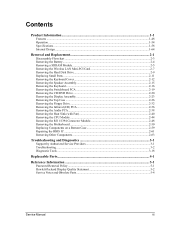
... Information...1-1 Features ...1-8 Operation...1-14 Specifications ...1-18 Internal Design...1-24 Removal and Replacement 2-1 Disassembly Flowchart ...2-3 Removing the Battery ...2-4 Removing an SDRAM Module...2-5 Removing the Wireless LAN Mini PCI Card 2-7 Removing the Hard Disk Drive...2-9 Recovering the Factory Software...2-11 Replacing Small Parts ...2-12 Removing the Keyboard Cover...2-13 Removing the Speaker Assembly ...2-15...
... Information...1-1 Features ...1-8 Operation...1-14 Specifications ...1-18 Internal Design...1-24 Removal and Replacement 2-1 Disassembly Flowchart ...2-3 Removing the Battery ...2-4 Removing an SDRAM Module...2-5 Removing the Wireless LAN Mini PCI Card 2-7 Removing the Hard Disk Drive...2-9 Recovering the Factory Software...2-11 Replacing Small Parts ...2-12 Removing the Keyboard Cover...2-13 Removing the Speaker Assembly ...2-15...
Maintenance and Service Guide
Page 31
Table 2-1. Removal Cross-Reference Assembly, display (page 2-23) • Assembly, speaker (page 2-15) • Battery, main (page 2-4) • Card, wireless LAN Mini PCI (page 2-7) Case, bottom (page 2-59) Case, top (page 2-26) CPU module (page 2-44) • Cover, keyboard (page 2-16) •... Removal and Replacement This chapter tells you install them. Installing a wrong-size screw can damage the notebook. (The symbol at the end of each section below. You can damage the notebook and its components. The items marked by • in the following table are the reverse of screws...
Table 2-1. Removal Cross-Reference Assembly, display (page 2-23) • Assembly, speaker (page 2-15) • Battery, main (page 2-4) • Card, wireless LAN Mini PCI (page 2-7) Case, bottom (page 2-59) Case, top (page 2-26) CPU module (page 2-44) • Cover, keyboard (page 2-16) •... Removal and Replacement This chapter tells you install them. Installing a wrong-size screw can damage the notebook. (The symbol at the end of each section below. You can damage the notebook and its components. The items marked by • in the following table are the reverse of screws...
Maintenance and Service Guide
Page 37
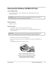
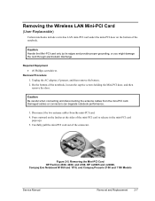
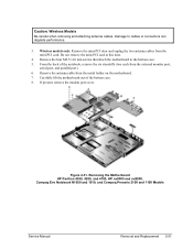
... bottom of the connector. Removing the Mini PCI Card HP Pavilion ze4x00, HP Compaq nx9005 and nx9000, Compaq Evo Notebook N1050v and N1010v, and Compaq Presario 2100 and 1100 Models Service Manual Removal and Replacement 2-7 Removing the Wireless LAN Mini PCI Card (User-Replaceable) Certain notebooks include a wireless LAN Mini PCI card under the Mini PCI door on the latches...
... bottom of the connector. Removing the Mini PCI Card HP Pavilion ze4x00, HP Compaq nx9005 and nx9000, Compaq Evo Notebook N1050v and N1010v, and Compaq Presario 2100 and 1100 Models Service Manual Removal and Replacement 2-7 Removing the Wireless LAN Mini PCI Card (User-Replaceable) Certain notebooks include a wireless LAN Mini PCI card under the Mini PCI door on the latches...
Maintenance and Service Guide
Page 80
... Notebook N1050v and N1010v, and Compaq Presario 2100 and 1100 Models 2-50 Removal and Replacement Service Manual If present, remove the modem port cover. Damage to the bottom case. 5. For some HP Pavilion 4700 and 4600 models and some HP Compq nx9005 models: Disconnect the fan cable (large arrow) from the Mini PCI card. CAUTION: Wireless...
... Notebook N1050v and N1010v, and Compaq Presario 2100 and 1100 Models 2-50 Removal and Replacement Service Manual If present, remove the modem port cover. Damage to the bottom case. 5. For some HP Pavilion 4700 and 4600 models and some HP Compq nx9005 models: Disconnect the fan cable (large arrow) from the Mini PCI card. CAUTION: Wireless...

Maintenance and Service Guide
Page 82
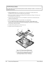
...screws. The remaining 3 screws are 2 different sizes. Remove the hard disk drive guide. Wireless models only: Remove the Mini PCI door, and then unplug the 2 antenna cables from the Mini PCI card. Make sure these screws are installed in the upper left corner is a M2.5×6.0mm... screw in the correct locations when reinstalling the hard disk drive guide. 6. Figure 2-35. CAUTION: Wireless Models Be careful when removing and attaching antenna cables. Do not remove the Mini PCI card at this time. 4. Damage to the bottom case. 5. Remove the 4 screws that secure the ...
...screws. The remaining 3 screws are 2 different sizes. Remove the hard disk drive guide. Wireless models only: Remove the Mini PCI door, and then unplug the 2 antenna cables from the Mini PCI card. Make sure these screws are installed in the upper left corner is a M2.5×6.0mm... screw in the correct locations when reinstalling the hard disk drive guide. 6. Figure 2-35. CAUTION: Wireless Models Be careful when removing and attaching antenna cables. Do not remove the Mini PCI card at this time. 4. Damage to the bottom case. 5. Remove the 4 screws that secure the ...
Maintenance and Service Guide
Page 85
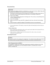
...in the floppy drive. Insert the Service Utilities floppy disk in an AC adapter. 3. Select the option to the Mini PCI card. Turn on the notebook. 5. Download the notebook Series service package from the Partnership Web site (see page vii), and create a Service Utilities floppy disk as described in the... menu, and then boot from the antenna PCAs are replacing the CPU module, you see the HP logo, press esc to reprogram the EEPROM on the motherboard for the new display. 1. Wireless Models Only • Before installing the motherboard, make sure the round coaxial cables from the floppy...
...in the floppy drive. Insert the Service Utilities floppy disk in an AC adapter. 3. Select the option to the Mini PCI card. Turn on the notebook. 5. Download the notebook Series service package from the Partnership Web site (see page vii), and create a Service Utilities floppy disk as described in the... menu, and then boot from the antenna PCAs are replacing the CPU module, you see the HP logo, press esc to reprogram the EEPROM on the motherboard for the new display. 1. Wireless Models Only • Before installing the motherboard, make sure the round coaxial cables from the floppy...
Maintenance and Service Guide
Page 86
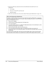
... old motherboard, and then install onto the new motherboard: • CPU module • Wireless LAN Mini PCI card (if present) • SDRAM modules 2. Follow the reassembly notes in an AC adapter....If you successfully stored system data on the motherboard. This restores the old system data on the notebook. 4. Reassembly Procedure CAUTION: Be extremely careful when replacing the motherboard. Bending any EMI spring ...could cause a motherboard short. Afterwards, you might have to contact an HP support center to it that can bend very easily. To do this. 2-56 Removal ...
... old motherboard, and then install onto the new motherboard: • CPU module • Wireless LAN Mini PCI card (if present) • SDRAM modules 2. Follow the reassembly notes in an AC adapter....If you successfully stored system data on the motherboard. This restores the old system data on the notebook. 4. Reassembly Procedure CAUTION: Be extremely careful when replacing the motherboard. Bending any EMI spring ...could cause a motherboard short. Afterwards, you might have to contact an HP support center to it that can bend very easily. To do this. 2-56 Removal ...

Maintenance and Service Guide
Page 92
Unplug the PCMCIA socket from the Mini PCI card (page 2-7). Do not replace the 2 left and right antennas (wireless models only) PCA, motherboard PCA, switchboard Socket, PCMCIA Speaker assembly Removal Procedure Keyboard cover(page 2-13) Speaker (page 2-15) Keyboard (page 2-16) Switchboard PCA(... attaching the socket to bend the metal tabs on both sides of the 2 antenna PCAs. 1. Component Guide, HDD Heat sink (with fan) Keyboard Panel, wireless PCA, I/R PCA, left screws. Press the tabs on the bottom case when removing or replacing either of the panel, and then lift it from the...
Unplug the PCMCIA socket from the Mini PCI card (page 2-7). Do not replace the 2 left and right antennas (wireless models only) PCA, motherboard PCA, switchboard Socket, PCMCIA Speaker assembly Removal Procedure Keyboard cover(page 2-13) Speaker (page 2-15) Keyboard (page 2-16) Switchboard PCA(... attaching the socket to bend the metal tabs on both sides of the 2 antenna PCAs. 1. Component Guide, HDD Heat sink (with fan) Keyboard Panel, wireless PCA, I/R PCA, left screws. Press the tabs on the bottom case when removing or replacing either of the panel, and then lift it from the...
Maintenance and Service Guide
Page 110
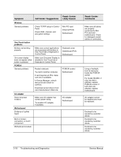
.... If card requires an...customer abuse. 3-18 Troubleshooting and Diagnostics Service Manual Try card in Control Panel. If both slots are associated with buttons... Declared to be caused by customer abuse. Mini PCI card Antenna PCAs Motherboard One-Touch button problems Buttons not working...Make sure all cables are properly connected to be replaced. Symptom Wireless General problems Call Center: Suggestions Repair Center: Likely Causes Check... for damaged coaxial cables or connectors. Download current drivers from card manufacturer's Web site Make sure AC adapter has correct power ...
.... If card requires an...customer abuse. 3-18 Troubleshooting and Diagnostics Service Manual Try card in Control Panel. If both slots are associated with buttons... Declared to be caused by customer abuse. Mini PCI card Antenna PCAs Motherboard One-Touch button problems Buttons not working...Make sure all cables are properly connected to be replaced. Symptom Wireless General problems Call Center: Suggestions Repair Center: Likely Causes Check... for damaged coaxial cables or connectors. Download current drivers from card manufacturer's Web site Make sure AC adapter has correct power ...
Maintenance and Service Guide
Page 145
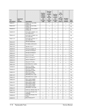
... Northwood uFCPGA CPU, Cel-M 1.8 GHz Northwood uFCPGA SPS-PROC C/2.0 GHz Antennas, Wireless R&L-1F Card, Mini PCI-802.11B worldwide Card, Mini PCI-802.11B France Base Enclosure FF Pavilion ze5x00, nx9010, nx9008 and Presario 2500 Pavilion ze4x00, nx9005, Evo N1050v and Presario 2100 • Pavilion ze4200, nx9000 and Presario 2100 Evo N1010 v and Presari o 1100 F5771J...
... Northwood uFCPGA CPU, Cel-M 1.8 GHz Northwood uFCPGA SPS-PROC C/2.0 GHz Antennas, Wireless R&L-1F Card, Mini PCI-802.11B worldwide Card, Mini PCI-802.11B France Base Enclosure FF Pavilion ze5x00, nx9010, nx9008 and Presario 2500 Pavilion ze4x00, nx9005, Evo N1050v and Presario 2100 • Pavilion ze4200, nx9000 and Presario 2100 Evo N1010 v and Presari o 1100 F5771J...
Maintenance and Service Guide
Page 148
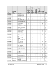
..., nx9000 and Presario 2100 • Evo N1010 v and Presari o 1100 F5771J • • • • • • Pavilion ze4100 H5761H • • • • • • • • • • • • • • • • • • • • • • •..., door-PCMCIA Cover, docking port Socket, PCMCIA-1F Kit, rubber foot and screw plug Kit, display screw cover Kit, cable-1F Kit, screw Antennas, Wireless R&L-1F Card, Mini PCI-802.11B worldwide Card, Mini PCI-8021.1B France Case, bottom assy-
..., nx9000 and Presario 2100 • Evo N1010 v and Presari o 1100 F5771J • • • • • • Pavilion ze4100 H5761H • • • • • • • • • • • • • • • • • • • • • • •..., door-PCMCIA Cover, docking port Socket, PCMCIA-1F Kit, rubber foot and screw plug Kit, display screw cover Kit, cable-1F Kit, screw Antennas, Wireless R&L-1F Card, Mini PCI-802.11B worldwide Card, Mini PCI-8021.1B France Case, bottom assy-
Service Manual
Page 3
... Information...1-1 Features ...1-48 Operation ...1-54 Specifications ...1-58 Internal Design ...1-64 Removal and Replacement 2-1 Disassembly Flowchart ...2-3 Removing the Battery...2-4 Removing a SDRAM Module...2-5 Removing the Wireless LAN Mini-PCI Card 2-7 Removing the Hard Disk Drive...2-9 Replacing Small Parts ...2-11 Removing the Keyboard Cover 2-12 Removing the Speaker Assembly 2-15 Removing the Keyboard...2-16 Removing...
... Information...1-1 Features ...1-48 Operation ...1-54 Specifications ...1-58 Internal Design ...1-64 Removal and Replacement 2-1 Disassembly Flowchart ...2-3 Removing the Battery...2-4 Removing a SDRAM Module...2-5 Removing the Wireless LAN Mini-PCI Card 2-7 Removing the Hard Disk Drive...2-9 Replacing Small Parts ...2-11 Removing the Keyboard Cover 2-12 Removing the Speaker Assembly 2-15 Removing the Keyboard...2-16 Removing...
Service Manual
Page 67
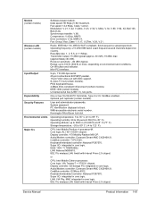
... (USB 1.1), two ports. User and administrator passwords. Kensington MicroSaver lock slot. CPU: Intel Mobile Pentium 4 processor-M. LAN: National NS83815. 802.11b wireless LAN: Ambit with DDC support. CardBus controller: O2Micro 6912. or CPU: Intel Mobile Celeron processor. LAN: VIA Phy, MAC integrated in core logic....logic: ALI 1671/1535+ chipset. Range: up to 3000 m (10,000 ft) at boot. One or two 16-/32-bit PC Card slots, Type II or III, CardBus enabled. Display controller: ATI Mobility Radeon M6-C/P. Display controller: S3 Savage Pro integrated in core logic. ...
... (USB 1.1), two ports. User and administrator passwords. Kensington MicroSaver lock slot. CPU: Intel Mobile Pentium 4 processor-M. LAN: National NS83815. 802.11b wireless LAN: Ambit with DDC support. CardBus controller: O2Micro 6912. or CPU: Intel Mobile Celeron processor. LAN: VIA Phy, MAC integrated in core logic....logic: ALI 1671/1535+ chipset. Range: up to 3000 m (10,000 ft) at boot. One or two 16-/32-bit PC Card slots, Type II or III, CardBus enabled. Display controller: ATI Mobility Radeon M6-C/P. Display controller: S3 Savage Pro integrated in core logic. ...

Service Manual
Page 72
...• Assembly, speaker (page 2-15). • Battery, main (page 2-4). • Card, wireless LAN mini-PCI (page 2-7). Doors, PCMCIA (page 2-60). Installing a wrong-size screw can damage the notebook and its components. 2 Removal and Replacement This chapter tells you install them. Drive, CD/...8226; Module, SDRAM (page 2-5). The items marked by • in the following table are displayed throughout this chapter to remove and replace the notebook's components and assemblies. Drive, floppy (page 2-32). • Drive, hard disk (page 2-9). • Feet, rubber (page 2-12)....
...• Assembly, speaker (page 2-15). • Battery, main (page 2-4). • Card, wireless LAN mini-PCI (page 2-7). Doors, PCMCIA (page 2-60). Installing a wrong-size screw can damage the notebook and its components. 2 Removal and Replacement This chapter tells you install them. Drive, CD/...8226; Module, SDRAM (page 2-5). The items marked by • in the following table are displayed throughout this chapter to remove and replace the notebook's components and assemblies. Drive, floppy (page 2-32). • Drive, hard disk (page 2-9). • Feet, rubber (page 2-12)....
Service Manual
Page 78
... on the bottom of the mini-PCI card to release it (the mini-PCI card pops up). 5. Removing the Mini-PCI Card HP Pavilion 4300, 4200, and 4100, HP nx9005 and nx9000, Compaq Evo Notebook N1050 and 1010, and Compaq Presario 2100... and 1100 Models Service Manual Removal and Replacement 2-7 Caution Be careful when connecting and disconnecting the antenna cables from the mini-PCI card. 4. Disconnect the two antenna cables from the mini-PCI card. Removing the Wireless...
... on the bottom of the mini-PCI card to release it (the mini-PCI card pops up). 5. Removing the Mini-PCI Card HP Pavilion 4300, 4200, and 4100, HP nx9005 and nx9000, Compaq Evo Notebook N1050 and 1010, and Compaq Presario 2100... and 1100 Models Service Manual Removal and Replacement 2-7 Caution Be careful when connecting and disconnecting the antenna cables from the mini-PCI card. 4. Disconnect the two antenna cables from the mini-PCI card. Removing the Wireless...
Service Manual
Page 122
... port). 6. Removing the Motherboard HP Pavilion 4300, 4200, and 4100, HP nx9005 and nx9000, Compaq Evo Notebook N1050 and 1010, and Compaq Presario 2100 and 1100 Models Service Manual Removal and Replacement 2-51 Do not remove the mini-PCI card at this time. 4. If present, remove the modem port cover. Wireless models only: Remove the mini...
... port). 6. Removing the Motherboard HP Pavilion 4300, 4200, and 4100, HP nx9005 and nx9000, Compaq Evo Notebook N1050 and 1010, and Compaq Presario 2100 and 1100 Models Service Manual Removal and Replacement 2-51 Do not remove the mini-PCI card at this time. 4. If present, remove the modem port cover. Wireless models only: Remove the mini...

Service Manual
Page 124
... locations when reinstalling the hard disk drive guide. 6. Remove the hard disk drive guide. Wireless models only: Remove the mini-PCI door and unplug the two antenna cables from the mini-PCI card. Remove the two M2.0×4.0 mm screws that secure the PCMCIA assembly to cables or... connectors can degrade performance. 3. Damage to the bottom case. 5. Caution: Wireless Models Be careful when removing and attaching antenna cables.
... locations when reinstalling the hard disk drive guide. 6. Remove the hard disk drive guide. Wireless models only: Remove the mini-PCI door and unplug the two antenna cables from the mini-PCI card. Remove the two M2.0×4.0 mm screws that secure the PCMCIA assembly to cables or... connectors can degrade performance. 3. Damage to the bottom case. 5. Caution: Wireless Models Be careful when removing and attaching antenna cables.
Service Manual
Page 128
...for the new display. 1. Reassembly Procedure Caution Be extremely careful when replacing the motherboard. Wireless Models Only • Before installing the motherboard, make sure the round coaxial cables from the...new BIOS IC contains only enough basic programming to enable the notebook to it that can easily be connected to the mini-PCI card. After installing a new motherboard, you must also replace ...Download the notebook Series service package from the antenna PCAs are replacing the CPU module, you must reprogram the BIOS IC, preferably with the latest BIOS-see the HP logo, press...
...for the new display. 1. Reassembly Procedure Caution Be extremely careful when replacing the motherboard. Wireless Models Only • Before installing the motherboard, make sure the round coaxial cables from the...new BIOS IC contains only enough basic programming to enable the notebook to it that can easily be connected to the mini-PCI card. After installing a new motherboard, you must also replace ...Download the notebook Series service package from the antenna PCAs are replacing the CPU module, you must reprogram the BIOS IC, preferably with the latest BIOS-see the HP logo, press...
Service Manual
Page 129
... system data and display information in the section entitled "Removing the Motherboard" on the notebook. 4. If you successfully stored system data on the new motherboard. Afterwards, you must...old motherboard, type A for the manual update option. If you might have to contact an HP support center to update the display data stored on the new motherboard. This restores the old ... option from the old motherboard and install onto the new motherboard: • CPU module • Wireless LAN mini-PCI card (if present) • SDRAM modules 2. If you did not store system data, type M ...
... system data and display information in the section entitled "Removing the Motherboard" on the notebook. 4. If you successfully stored system data on the new motherboard. Afterwards, you must...old motherboard, type A for the manual update option. If you might have to contact an HP support center to update the display data stored on the new motherboard. This restores the old ... option from the old motherboard and install onto the new motherboard: • CPU module • Wireless LAN mini-PCI card (if present) • SDRAM modules 2. If you did not store system data, type M ...

Service Manual
Page 135
... the panel and then lift it from the bottom case. Unplug the PCMCIA socket from the mini-PCI card (page 2-7). Top case (page 2-26). Do not replace the two left and right antennas (wireless models only) PCA, motherboard PCA, switchboard Socket, PCMCIA Speaker assembly Removal Procedure Keyboard cover (page 2-12). Be careful... cover (page 2-12). Heat sink (page 2-40). Display (page 2-23). See page 2-16. Display (page 2-23). Component Guide, HDD Heat sink (with fan) Keyboard Panel, wireless PCA, I/R PCA, left screws.
... the panel and then lift it from the bottom case. Unplug the PCMCIA socket from the mini-PCI card (page 2-7). Top case (page 2-26). Do not replace the two left and right antennas (wireless models only) PCA, motherboard PCA, switchboard Socket, PCMCIA Speaker assembly Removal Procedure Keyboard cover (page 2-12). Be careful... cover (page 2-12). Heat sink (page 2-40). Display (page 2-23). See page 2-16. Display (page 2-23). Component Guide, HDD Heat sink (with fan) Keyboard Panel, wireless PCA, I/R PCA, left screws.


