Maintenance and Service Guide
Page 3
... ...2-26 Removing the Floppy Drive...2-32 Removing the Infrared (I/R) PCA...2-36 Removing the Audio PCA ...2-38 Removing the Heat Sink (with Fan 2-40 Removing the CPU Module ...2-44 Removing the RJ11/1394 Connector Module 2-48 Removing the Motherboard ...2-50 Replacing Components on a Bottom Case 2-59 Repairing the BIOS IC...2-61 Removing...
... ...2-26 Removing the Floppy Drive...2-32 Removing the Infrared (I/R) PCA...2-36 Removing the Audio PCA ...2-38 Removing the Heat Sink (with Fan 2-40 Removing the CPU Module ...2-44 Removing the RJ11/1394 Connector Module 2-48 Removing the Motherboard ...2-50 Replacing Components on a Bottom Case 2-59 Repairing the BIOS IC...2-61 Removing...
Maintenance and Service Guide
Page 4
...2-33 Figure 2-23. Removing the Floppy Drive 2-35 Figure 2-24. Removing the Heat Sink (with Fan 2-41 Figure 2-27. Intel CPU Module Removal 2-45 Figure 2-29. Removing the Motherboard 2-51 Figure 2-35. Figures Figure 1-1. Removing the Top Case...2-31 Figure 2-22....the CPU Module 2-39 Figure 2-33. Removing the RJ11/1394 Connector Module 2-49 Figure 2-34. Removing the I/R PCA...2-37 Figure 2-25. Removing the Audio PCA ...2-39 Figure 2-26. Front View...1-8 Figure 1-2. Bottom View...1-10 Figure 1-4. Back View ...1-12 Figure 1-6. Resetting the Notebook ...
...2-33 Figure 2-23. Removing the Floppy Drive 2-35 Figure 2-24. Removing the Heat Sink (with Fan 2-41 Figure 2-27. Intel CPU Module Removal 2-45 Figure 2-29. Removing the Motherboard 2-51 Figure 2-35. Figures Figure 1-1. Removing the Top Case...2-31 Figure 2-22....the CPU Module 2-39 Figure 2-33. Removing the RJ11/1394 Connector Module 2-49 Figure 2-34. Removing the I/R PCA...2-37 Figure 2-25. Removing the Audio PCA ...2-39 Figure 2-26. Front View...1-8 Figure 1-2. Bottom View...1-10 Figure 1-4. Back View ...1-12 Figure 1-6. Resetting the Notebook ...
Maintenance and Service Guide
Page 29
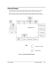
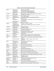
Table 1-8 on page 1-25 lists the roles that these modules play in virtually all system functions. The following figure shows the connections among the notebook's replaceable electronic modules. Internal Design The motherboard PCA is the central component of the notebook's design. Replaceable Module Diagram Service Manual Product Information 1-23 The CPU module and most other subsystems connect to the motherboard. It plays a role in the notebook's functional subsystems. Figure 1-8.
Table 1-8 on page 1-25 lists the roles that these modules play in virtually all system functions. The following figure shows the connections among the notebook's replaceable electronic modules. Internal Design The motherboard PCA is the central component of the notebook's design. Replaceable Module Diagram Service Manual Product Information 1-23 The CPU module and most other subsystems connect to the motherboard. It plays a role in the notebook's functional subsystems. Figure 1-8.
Maintenance and Service Guide
Page 30
... Motherboard Hard disk drive Floppy drive CPU module Motherboard Motherboard SDRAM module Battery Motherboard Switchboard PCA AC adapter Motherboard SDRAM module Display assembly Motherboard Hard disk drive Motherboard Floppy drive Motherboard Switchboard ...
... Motherboard Hard disk drive Floppy drive CPU module Motherboard Motherboard SDRAM module Battery Motherboard Switchboard PCA AC adapter Motherboard SDRAM module Display assembly Motherboard Hard disk drive Motherboard Floppy drive Motherboard Switchboard ...
Maintenance and Service Guide
Page 31
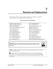
... an M2.5×4.0mm T-head screw). Service Manual Removal and Replacement 2-1 Without proper grounding, an electrostatic discharge can damage the notebook. (The symbol at the end of each section below. Symbols like these to verify the sizes of the removal steps. Removal... speaker (page 2-15) • Battery, main (page 2-4) • Card, wireless LAN Mini PCI (page 2-7) Case, bottom (page 2-59) Case, top (page 2-26) CPU module (page 2-44) • Cover, keyboard (page 2-16) • Door, Mini PCI (page 2-7) • Door, SDRAM (page 2-5) Doors, PCMCIA (page 2-60) Drive...
... an M2.5×4.0mm T-head screw). Service Manual Removal and Replacement 2-1 Without proper grounding, an electrostatic discharge can damage the notebook. (The symbol at the end of each section below. Symbols like these to verify the sizes of the removal steps. Removal... speaker (page 2-15) • Battery, main (page 2-4) • Card, wireless LAN Mini PCI (page 2-7) Case, bottom (page 2-59) Case, top (page 2-26) CPU module (page 2-44) • Cover, keyboard (page 2-16) • Door, Mini PCI (page 2-7) • Door, SDRAM (page 2-5) Doors, PCMCIA (page 2-60) Drive...
Maintenance and Service Guide
Page 71
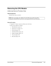
...) • Heat sink (page 2-40) Service Manual Removal and Replacement 2-41 Removal Procedure 1. Removing the CPU Module (Authorized Service Providers Only) Required Equipment Small flat-blade (3mm) screwdriver NOTE: This section applies only to HP Pavilion 4x00, HP Compaq nx9005 and nx9000, Compaq Evo Notebook N1050v and N1010v, and Compaq Presario 2100 and 1100 models.
...) • Heat sink (page 2-40) Service Manual Removal and Replacement 2-41 Removal Procedure 1. Removing the CPU Module (Authorized Service Providers Only) Required Equipment Small flat-blade (3mm) screwdriver NOTE: This section applies only to HP Pavilion 4x00, HP Compaq nx9005 and nx9000, Compaq Evo Notebook N1050v and N1010v, and Compaq Presario 2100 and 1100 models.

Maintenance and Service Guide
Page 72
... one -half turn clockwise to carefully remove the old thermal pad from the heat sink, and then attach the new thermal pad. Figure 2-28. Intel CPU Module Removal HP Pavilion 4x00, HP Compaq nx9005 and nx9000, Compaq Evo Notebook N1050v and N1010v, and Compaq Presario 2100 and 1100 Models CAUTION: Each time you install a new...
... one -half turn clockwise to carefully remove the old thermal pad from the heat sink, and then attach the new thermal pad. Figure 2-28. Intel CPU Module Removal HP Pavilion 4x00, HP Compaq nx9005 and nx9000, Compaq Evo Notebook N1050v and N1010v, and Compaq Presario 2100 and 1100 Models CAUTION: Each time you install a new...

Maintenance and Service Guide
Page 73
... shown in Figure 2-29 and move the screwdriver in the directon shown by the arrow until a Select is felt or heard. AMD CPU Module Removal HP Pavilion 4x00, HP Compaq nx9005 and nx9000, Compaq Evo Notebook N1050v and N1010v, and Compaq Presario 2100 and 1100 Models Service Manual Removal and Replacement 2-43 4. Figure 2-29 AMD...
... shown in Figure 2-29 and move the screwdriver in the directon shown by the arrow until a Select is felt or heard. AMD CPU Module Removal HP Pavilion 4x00, HP Compaq nx9005 and nx9000, Compaq Evo Notebook N1050v and N1010v, and Compaq Presario 2100 and 1100 Models Service Manual Removal and Replacement 2-43 4. Figure 2-29 AMD...

Maintenance and Service Guide
Page 74
...inserted only in the illustration below to secure the CPU module into the position shown in Figure 2-31 and move as indicated by the arrow in one way). AMD CPU Module Installation HP Pavilion 4x00, HP Compaq nx9005 and nx9000, Compaq Evo Notebook N1050v and N1010v, and Compaq Presario 2100 and ...1100 Models CAUTION: Each time you install a new CPU module, you must also replace the heat sink's thermal pad...
...inserted only in the illustration below to secure the CPU module into the position shown in Figure 2-31 and move as indicated by the arrow in one way). AMD CPU Module Installation HP Pavilion 4x00, HP Compaq nx9005 and nx9000, Compaq Evo Notebook N1050v and N1010v, and Compaq Presario 2100 and ...1100 Models CAUTION: Each time you install a new CPU module, you must also replace the heat sink's thermal pad...

Maintenance and Service Guide
Page 76
Removing the CPU Module HP Pavilion ze5x00, HP nx9010 and HPnx9008, and Compaq Presario 2500 Models CAUTION: Each time you install a new CPU module, you must also replace the heat sink's thermal pad to replace the thermal pad on the heat sink, as described in the Caution above. 2-... Notes Figure 2-32. Slide the front tip of its socket on the right side of the CPU module socket secures the locking arm. • Be sure to maintain optimum heat transfer. Carefully lift the CPU module off of the locking arm slightly to carefully remove the old thermal pad from the heat...
Removing the CPU Module HP Pavilion ze5x00, HP nx9010 and HPnx9008, and Compaq Presario 2500 Models CAUTION: Each time you install a new CPU module, you must also replace the heat sink's thermal pad to replace the thermal pad on the heat sink, as described in the Caution above. 2-... Notes Figure 2-32. Slide the front tip of its socket on the right side of the CPU module socket secures the locking arm. • Be sure to maintain optimum heat transfer. Carefully lift the CPU module off of the locking arm slightly to carefully remove the old thermal pad from the heat...
Maintenance and Service Guide
Page 85
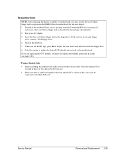
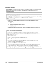
Reassembly Notes NOTE: After replacing the display assembly or motherboard, you must also replace the thermal pad on the motherboard. Download the notebook Series service package from the Partnership Web site (see page vii), and create a Service Utilities floppy disk as described in an AC adapter. 3. ...Select the option to update the display/LCD identification stored on the heat sink (see the HP logo, press esc to display the boot menu, and then boot from the antenna PCAs are replacing the CPU module, you must use the Service Utilities floppy disk to the Mini PCI card. Wireless Models...
Reassembly Notes NOTE: After replacing the display assembly or motherboard, you must also replace the thermal pad on the motherboard. Download the notebook Series service package from the Partnership Web site (see page vii), and create a Service Utilities floppy disk as described in an AC adapter. 3. ...Select the option to update the display/LCD identification stored on the heat sink (see the HP logo, press esc to display the boot menu, and then boot from the antenna PCAs are replacing the CPU module, you must use the Service Utilities floppy disk to the Mini PCI card. Wireless Models...
Maintenance and Service Guide
Page 86
... from the boot menu. 6. Insert the Service Utilities floppy disk in the EEPROM on the motherboard. Afterwards, you might have to contact an HP support center to update the display data stored on the new motherboard. After installing a new motherboard, you hear 5 beeps, press F1 to do... then install onto the new motherboard: • CPU module • Wireless LAN Mini PCI card (if present) • SDRAM modules 2. This restores the old system data on the notebook. 4. Enter the serial number from the bottom of the notebook-you must reprogram the BIOS IC, preferably with the...
... from the boot menu. 6. Insert the Service Utilities floppy disk in the EEPROM on the motherboard. Afterwards, you might have to contact an HP support center to update the display data stored on the new motherboard. After installing a new motherboard, you hear 5 beeps, press F1 to do... then install onto the new motherboard: • CPU module • Wireless LAN Mini PCI card (if present) • SDRAM modules 2. This restores the old system data on the notebook. 4. Enter the serial number from the bottom of the notebook-you must reprogram the BIOS IC, preferably with the...
Maintenance and Service Guide
Page 91
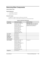
Table 2-5. Removing Components Component Battery, CMOS Case, bottom Case, top CD/DVD drive CPU module Display assembly Doors, PCMCIA Floppy drive Removal Procedure Keyboard cover(page 2-13) Speaker (page 2-15) Keyboard (page 2-16) Switchboard PCA(page 2-19) CD/DVD (...
Table 2-5. Removing Components Component Battery, CMOS Case, bottom Case, top CD/DVD drive CPU module Display assembly Doors, PCMCIA Floppy drive Removal Procedure Keyboard cover(page 2-13) Speaker (page 2-15) Keyboard (page 2-16) Switchboard PCA(page 2-19) CD/DVD (...
Maintenance and Service Guide
Page 100
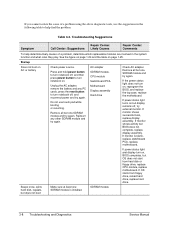
...If monitor shows successful boot, replace display assembly. If monitor is installed. If OS starts from hard disk or floppy drive, replace CPU module, replace motherboard. SDRAM module Check AC adapter. Do not use the suggestions in the following table to help determine likely causes...involved in the system function and what roles they play. Reinsert any PC cards, press the reset button to turn notebook off, and reconnect power and try again. If power status light and display turn notebook off , try again. Troubleshooting Suggestions Symptom Call Center: Suggestions Repair ...
...If monitor shows successful boot, replace display assembly. If monitor is installed. If OS starts from hard disk or floppy drive, replace CPU module, replace motherboard. SDRAM module Check AC adapter. Do not use the suggestions in the following table to help determine likely causes...involved in the system function and what roles they play. Reinsert any PC cards, press the reset button to turn notebook off, and reconnect power and try again. If power status light and display turn notebook off , try again. Troubleshooting Suggestions Symptom Call Center: Suggestions Repair ...
Maintenance and Service Guide
Page 103
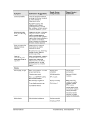
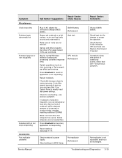
... Never. Adjust display brightness. Display cable connection SDRAM modules CPU module Display assembly Motherboard White display Adjust display brightness. Display assembly Switchboard PCA Repair Center: Comments Check cable connections. Notebook can take a minute or longer to resume if network ...card is installed properly, replace CPU module. Try external monitor. Make sure CPU module is installed. Notebook won't suspend if connection to another computer is...
... Never. Adjust display brightness. Display cable connection SDRAM modules CPU module Display assembly Motherboard White display Adjust display brightness. Display assembly Switchboard PCA Repair Center: Comments Check cable connections. Notebook can take a minute or longer to resume if network ...card is installed properly, replace CPU module. Try external monitor. Make sure CPU module is installed. Notebook won't suspend if connection to another computer is...
Maintenance and Service Guide
Page 111
...virus scanning or file browsers) can hear this). Reset notebook (see previous symptom. Check heat sink for 24 hours to see previous symptom. CMOS battery Motherboard Heat sink CPU module Motherboard Check notebook's power supply. Make sure air vents are not blocked....replicator Motherboard Repair Center: Comments Charge CMOS battery. Check thermal contact between CPU and heat sink. Symptom Miscellaneous Clock loses time Notebook gets abnormally hot Notebook pauses or runs sluggishly Notebook still on but stops responding Accessories Port replicator problems Call Center: Suggestions ...
...virus scanning or file browsers) can hear this). Reset notebook (see previous symptom. Check heat sink for 24 hours to see previous symptom. CMOS battery Motherboard Heat sink CPU module Motherboard Check notebook's power supply. Make sure air vents are not blocked....replicator Motherboard Repair Center: Comments Charge CMOS battery. Check thermal contact between CPU and heat sink. Symptom Miscellaneous Clock loses time Notebook gets abnormally hot Notebook pauses or runs sluggishly Notebook still on but stops responding Accessories Port replicator problems Call Center: Suggestions ...
Maintenance and Service Guide
Page 114
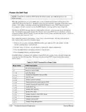
...(the default setting), press esc during boot to restart with initial POST values Set IN POST flag Initialize CPU registers Enable CPU cache Initialize caches to start the notebook. POST indicates progress by performing a "clean" boot, as a hardware, software, or firmware failure. ...Note that not all accessories, including SDRAM modules, port replicator, PC cards, printer, external monitor, pointing device, and keyboard. 2. ...
...(the default setting), press esc during boot to restart with initial POST values Set IN POST flag Initialize CPU registers Enable CPU cache Initialize caches to start the notebook. POST indicates progress by performing a "clean" boot, as a hardware, software, or firmware failure. ...Note that not all accessories, including SDRAM modules, port replicator, PC cards, printer, external monitor, pointing device, and keyboard. 2. ...
Maintenance and Service Guide
Page 115
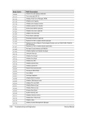
... all video adapters in system QuietBoot start shut down Shadow system BIOS ROM Auto size cache Advanced configuration of memory bus Test CPU bus-clock frequency Initialize Phoenix Dispatch Manager Warm start (optional) Shadow video BIOS ROM Display BIOS copyright notice Troubleshooting and Diagnostics ...BIOS shadow RAM failure on data bits xxxx of high byte of chipset registers Load alternate registers with initial POST values Restore CPU control word during warm boot Initialize PCI Bus Mastering devices Initialize keyboard controller BIOS ROM checksum Initialize cache before memory Auto ...
... all video adapters in system QuietBoot start shut down Shadow system BIOS ROM Auto size cache Advanced configuration of memory bus Test CPU bus-clock frequency Initialize Phoenix Dispatch Manager Warm start (optional) Shadow video BIOS ROM Display BIOS copyright notice Troubleshooting and Diagnostics ...BIOS shadow RAM failure on data bits xxxx of high byte of chipset registers Load alternate registers with initial POST values Restore CPU control word during warm boot Initialize PCI Bus Mastering devices Initialize keyboard controller BIOS ROM checksum Initialize cache before memory Auto ...
Maintenance and Service Guide
Page 116
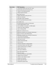
... extended memory Test extended memory address lines Jump to UserPatch1 Configure advanced cache registers Initialize Multi Processor APIC Enable external and CPU caches Set up System Management Mode (SMM) area Display external L2 cache size Load custom defaults (optional) Display shadow-...device initialization Detect and install external RS232 ports Configure non-MCD IDE controllers Detect and install external parallel ports Initialize PC-compatible PnP ISA devices Re-initialize onboard I/O ports Configure Motherboard Configurable Devices (optional) Initialize BIOS Data Area 3-24 Troubleshooting ...
... extended memory Test extended memory address lines Jump to UserPatch1 Configure advanced cache registers Initialize Multi Processor APIC Enable external and CPU caches Set up System Management Mode (SMM) area Display external L2 cache size Load custom defaults (optional) Display shadow-...device initialization Detect and install external RS232 ports Configure non-MCD IDE controllers Detect and install external parallel ports Initialize PC-compatible PnP ISA devices Re-initialize onboard I/O ports Configure Motherboard Configurable Devices (optional) Initialize BIOS Data Area 3-24 Troubleshooting ...
Maintenance and Service Guide
Page 118
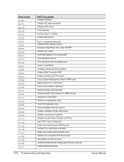
... enable remote serial video Re-map I/O and memory for PCMCIA Initialize digitizer and display message Unknown interrupt Initialize the chipset Initialize the bridge Initialize the CPU Initialize system timer Initialize system I/O Check force recovery boot Checksum BIOS ROM Go to BIOS Set Huge Segment Initialize Multi Processor Initialize OEM special code...
... enable remote serial video Re-map I/O and memory for PCMCIA Initialize digitizer and display message Unknown interrupt Initialize the chipset Initialize the bridge Initialize the CPU Initialize system timer Initialize system I/O Check force recovery boot Checksum BIOS ROM Go to BIOS Set Huge Segment Initialize Multi Processor Initialize OEM special code...


