HP LaserJet P3005 - User Guide
Page 115
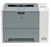
...● Press a device ● Turn the device ● Make sure that the power supplied to see Solve common Macintosh problems. Step 1: Does READY appear on the control-panel display? the appropriate panel &#... step 3. NOTE Macintosh users: For more problem-solving information, see if the device connections and the power responds. The display is selected at the device control panel. When XXX MB appears on . Problem-... lights stay language is in this guide, contact an HP-authorized service or support provider. Press to scroll through the available languages.
...● Press a device ● Turn the device ● Make sure that the power supplied to see Solve common Macintosh problems. Step 1: Does READY appear on the control-panel display? the appropriate panel &#... step 3. NOTE Macintosh users: For more problem-solving information, see if the device connections and the power responds. The display is selected at the device control panel. When XXX MB appears on . Problem-... lights stay language is in this guide, contact an HP-authorized service or support provider. Press to scroll through the available languages.

HP LaserJet P3005 - User Guide
Page 147
... Do not print on both sides of media at a time. ● If you are printing small sizes (such as index cards), make sure that the power supplied to feed through the device from tray 1, try rotating the stack 180°. ● Try rotating media to the device is oriented correctly in the... device and can void warranty. ● Make sure that the media is steady and meets device specifications. See Clean the device. ● Contact an HP-authorized service or support provider to separate each sheet. See Specifications. ● Clean the device. See the support flyer that meets...
... Do not print on both sides of media at a time. ● If you are printing small sizes (such as index cards), make sure that the power supplied to feed through the device from tray 1, try rotating the stack 180°. ● Try rotating media to the device is oriented correctly in the... device and can void warranty. ● Make sure that the media is steady and meets device specifications. See Clean the device. ● Contact an HP-authorized service or support provider to separate each sheet. See Specifications. ● Clean the device. See the support flyer that meets...

Service Manual
Page 7
... ...72 Top, right cover ...73 Top cover ...74 Front, right cover ...75 Control panel ...78 Formatter ...80 Fuser ...83 Laser/scanner ...86 Engine control unit (ECU) ...88 Access plate ...96 High-voltage power supply ...97 Paper feed guide assembly ...104 Main motor ...106 Gear assembly ...108 Reinstallation notes for the gear assembly 110...
... ...72 Top, right cover ...73 Top cover ...74 Front, right cover ...75 Control panel ...78 Formatter ...80 Fuser ...83 Laser/scanner ...86 Engine control unit (ECU) ...88 Access plate ...96 High-voltage power supply ...97 Paper feed guide assembly ...104 Main motor ...106 Gear assembly ...108 Reinstallation notes for the gear assembly 110...

Service Manual
Page 15
... 4-1 Systems overview ...46 Figure 4-2 Print engine general structure ...47 Figure 4-3 Engine control system circuit diagram 48 Figure 4-4 Low-voltage power supply circuit diagram 49 Figure 4-5 Pickup/feed/delivery system ...50 Figure 4-6 Laser/scanner system ...51 Figure 4-7 Print cartridge diagram ...52 Figure 4-8 Image-formation system ...52 Figure 4-9 Primary charging ...53 Figure 4-10...Removing the fuser (1 of 3) ...83 Figure 5-17 Removing the fuser (2 of 3) ...84 Figure 5-18 Removing the fuser (3 of 3) ...85 Figure 5-19 Removing the laser/scanner (1 of 2 86 Figure 5-20 Removing the...
... 4-1 Systems overview ...46 Figure 4-2 Print engine general structure ...47 Figure 4-3 Engine control system circuit diagram 48 Figure 4-4 Low-voltage power supply circuit diagram 49 Figure 4-5 Pickup/feed/delivery system ...50 Figure 4-6 Laser/scanner system ...51 Figure 4-7 Print cartridge diagram ...52 Figure 4-8 Image-formation system ...52 Figure 4-9 Primary charging ...53 Figure 4-10...Removing the fuser (1 of 3) ...83 Figure 5-17 Removing the fuser (2 of 3) ...84 Figure 5-18 Removing the fuser (3 of 3) ...85 Figure 5-19 Removing the laser/scanner (1 of 2 86 Figure 5-20 Removing the...

Service Manual
Page 16
... 2 96 Figure 5-30 Removing the access plate (2 of 2 96 Figure 5-31 Removing the power supply (1 of 5 97 Figure 5-32 Removing the power supply (2 of 5 98 Figure 5-33 Removing the power supply (3 of 5 99 Figure 5-34 Removing the power supply (4 of 5 100 Figure 5-35 Removing the power supply (5 of 5 101 Figure 5-36 Grounding-spring locations ...102 Figure 5-37 Reinstalling the oblique...
... 2 96 Figure 5-30 Removing the access plate (2 of 2 96 Figure 5-31 Removing the power supply (1 of 5 97 Figure 5-32 Removing the power supply (2 of 5 98 Figure 5-33 Removing the power supply (3 of 5 99 Figure 5-34 Removing the power supply (4 of 5 100 Figure 5-35 Removing the power supply (5 of 5 101 Figure 5-36 Grounding-spring locations ...102 Figure 5-37 Reinstalling the oblique...

Service Manual
Page 65
... (ECU) The ECU coordinates all device functions, according to the pickup/ feed/delivery system, the laser/scanner system, and the image-formation system. Figure 4-4 Low-voltage power supply circuit diagram on page 49 shows the low-voltage power supply circuit on page 47 shows the relationship of the ECU to commands that the formatter sends...
... (ECU) The ECU coordinates all device functions, according to the pickup/ feed/delivery system, the laser/scanner system, and the image-formation system. Figure 4-4 Low-voltage power supply circuit diagram on page 49 shows the low-voltage power supply circuit on page 47 shows the relationship of the ECU to commands that the formatter sends...

Service Manual
Page 81
5 Removal and replacement Chapter contents ● Overview ● Service approach ● Covers ● Control panel ● Formatter ● Fuser ● Laser/scanner ● Engine control unit (ECU) ● Access plate ● High-voltage power supply ● Paper feed guide assembly ● Main motor ● Gear assembly ● Reinstallation notes for the gear assembly ●...
5 Removal and replacement Chapter contents ● Overview ● Service approach ● Covers ● Control panel ● Formatter ● Fuser ● Laser/scanner ● Engine control unit (ECU) ● Access plate ● High-voltage power supply ● Paper feed guide assembly ● Main motor ● Gear assembly ● Reinstallation notes for the gear assembly ●...

Service Manual
Page 86
... and replacement ENWW Back cover Fuser I/O cover Right side cover Top, right cover Top cover Laser/scanner assembly Front, right cover Control panel Fan, right side ECU Main gear assembly Fuser Duplex access plate High-voltage power supply Paper feed guide assembly Main motor Left side cover Figure 5-1 Parts removal diagram After performing...
... and replacement ENWW Back cover Fuser I/O cover Right side cover Top, right cover Top cover Laser/scanner assembly Front, right cover Control panel Fan, right side ECU Main gear assembly Fuser Duplex access plate High-voltage power supply Paper feed guide assembly Main motor Left side cover Figure 5-1 Parts removal diagram After performing...

Service Manual
Page 115
At the right side of the device, remove one grounding screw from inside the slot (callout 1). 1 Figure 5-31 Removing the power supply (1 of 5) ENWW High-voltage power supply 97 Remove the following components: ● All covers (see Covers on page 69) ● Formatter (see Formatter on page 80) ● ECU (see Engine control unit (ECU) on page 88) ● Access plate (see Access plate on page 96). 2. High-voltage power supply 1.
At the right side of the device, remove one grounding screw from inside the slot (callout 1). 1 Figure 5-31 Removing the power supply (1 of 5) ENWW High-voltage power supply 97 Remove the following components: ● All covers (see Covers on page 69) ● Formatter (see Formatter on page 80) ● ECU (see Engine control unit (ECU) on page 88) ● Access plate (see Access plate on page 96). 2. High-voltage power supply 1.

Service Manual
Page 116
At the left side of the device, disconnect one grounding clip (callout 2), thread the clip through the hole in the device chassis, and then remove two screws (callout 3). 3 2 Figure 5-32 Removing the power supply (2 of the device facing you. 98 Chapter 5 Removal and replacement ENWW 3. Carefully tip the device so that it rests on its top, with the front of 5) Reinstallation tip Remember how the cable is threaded and connected to the device. 4.
At the left side of the device, disconnect one grounding clip (callout 2), thread the clip through the hole in the device chassis, and then remove two screws (callout 3). 3 2 Figure 5-32 Removing the power supply (2 of the device facing you. 98 Chapter 5 Removal and replacement ENWW 3. Carefully tip the device so that it rests on its top, with the front of 5) Reinstallation tip Remember how the cable is threaded and connected to the device. 4.

Service Manual
Page 117
At the bottom of the device, remove the two screws (callout 4) that secure the oblique-roller assembly to the device, and then lift the assembly from the device. 4 Figure 5-33 Removing the power supply (3 of 5) ENWW High-voltage power supply 99 5.
At the bottom of the device, remove the two screws (callout 4) that secure the oblique-roller assembly to the device, and then lift the assembly from the device. 4 Figure 5-33 Removing the power supply (3 of 5) ENWW High-voltage power supply 99 5.

Service Manual
Page 118
Remove the remaining three screws (callout 7) from the ribbon-cable protector (callout 6) and then lift the protector out of the device. 7 5 6 Figure 5-34 Removing the power supply (4 of 5) 7. Remove two screws (callout 5) from the power-supply pan. 100 Chapter 5 Removal and replacement ENWW 6.
Remove the remaining three screws (callout 7) from the ribbon-cable protector (callout 6) and then lift the protector out of the device. 7 5 6 Figure 5-34 Removing the power supply (4 of 5) 7. Remove two screws (callout 5) from the power-supply pan. 100 Chapter 5 Removal and replacement ENWW 6.

Service Manual
Page 119
With the device upside down and with the rear of the device facing you, lift the edge of the powersupply pan farthest from you up slightly, slide it to the right, lift the edge at the left, unroute the cables, and then disconnect two cables (callout 8). 8 Figure 5-35 Removing the power supply (5 of 5) ENWW High-voltage power supply 101 8.
With the device upside down and with the rear of the device facing you, lift the edge of the powersupply pan farthest from you up slightly, slide it to the right, lift the edge at the left, unroute the cables, and then disconnect two cables (callout 8). 8 Figure 5-35 Removing the power supply (5 of 5) ENWW High-voltage power supply 101 8.

Service Manual
Page 120
9. You might need to reinstall the spring before reinstalling the power supply. 9 Figure 5-36 Grounding-spring locations Reinstallation tip To reinstall the oblique-roller assembly, slide the tab (callout 10) in first and then insert the other side of the device to align the gears. Rotate the roller toward the back of the assembly. Verify that the roller lever (callout 11) is not misaligned. 102 Chapter 5 Removal and replacement ENWW As you remove the power supply, note the location of the non-captive grounding spring (callout 9).
9. You might need to reinstall the spring before reinstalling the power supply. 9 Figure 5-36 Grounding-spring locations Reinstallation tip To reinstall the oblique-roller assembly, slide the tab (callout 10) in first and then insert the other side of the device to align the gears. Rotate the roller toward the back of the assembly. Verify that the roller lever (callout 11) is not misaligned. 102 Chapter 5 Removal and replacement ENWW As you remove the power supply, note the location of the non-captive grounding spring (callout 9).

Service Manual
Page 121
11 10 Figure 5-37 Reinstalling the oblique-roller assembly NOTE The power supply and the power-supply pan together are a single FRU. You do not have to separate the power supply and the power-supply pan. ENWW High-voltage power supply 103
11 10 Figure 5-37 Reinstalling the oblique-roller assembly NOTE The power supply and the power-supply pan together are a single FRU. You do not have to separate the power supply and the power-supply pan. ENWW High-voltage power supply 103

Service Manual
Page 122
Lift one non-captive grounding spring (see High-voltage power supply on page 102 out of the assembly farthest from you, lift the right corner up, twist the assembly counterclockwise, and remove the assembly from the ... control unit (ECU) on page 88) ● Access plate (see Access plate on page 96). ● Fuser (see Fuser on page 83) ● High-voltage power supply (see callout 11 in Figure 5-36 Grounding-spring locations on page 97) 2. Remove two screws (callout 2). 2 1 Figure 5-38 Removing the paper feed guide assembly 5. Loosen...
Lift one non-captive grounding spring (see High-voltage power supply on page 102 out of the assembly farthest from you, lift the right corner up, twist the assembly counterclockwise, and remove the assembly from the ... control unit (ECU) on page 88) ● Access plate (see Access plate on page 96). ● Fuser (see Fuser on page 83) ● High-voltage power supply (see callout 11 in Figure 5-36 Grounding-spring locations on page 97) 2. Remove two screws (callout 2). 2 1 Figure 5-38 Removing the paper feed guide assembly 5. Loosen...

Service Manual
Page 124
... control unit (ECU) on page 88) ● Access plate (see Access plate on page 96). ● Fuser (see Fuser on page 83) ● High-voltage power supply (see High-voltage power supply on page 97) ● Paper feed guide assembly (see Paper feed guide assembly on page 104. 2.
... control unit (ECU) on page 88) ● Access plate (see Access plate on page 96). ● Fuser (see Fuser on page 83) ● High-voltage power supply (see High-voltage power supply on page 97) ● Paper feed guide assembly (see Paper feed guide assembly on page 104. 2.

Service Manual
Page 126
... on page 69) ● Formatter (see Formatter on page 80) ● ECU (see Engine control unit (ECU) on page 88) ● High-voltage power supply (see High-voltage power supply on page 97) 2. Remove the two switch link assembly screws (callout 1), slide the assembly toward the front of the device, and then lift it...
... on page 69) ● Formatter (see Formatter on page 80) ● ECU (see Engine control unit (ECU) on page 88) ● High-voltage power supply (see High-voltage power supply on page 97) 2. Remove the two switch link assembly screws (callout 1), slide the assembly toward the front of the device, and then lift it...

Service Manual
Page 130
Remove one screw (callout 1). 1 Figure 5-45 Removing the tray 2 solenoid 3. Lift the solenoid off of the device chassis. 112 Chapter 5 Removal and replacement ENWW Remove the following components: ● All covers (see Covers on page 69) ● Formatter (see Formatter on page 80) ● ECU (see Engine control unit (ECU) on page 88) ● High-voltage power supply (see High-voltage power supply on page 97) ● Gear assembly (see Gear assembly on page 108) 2. Tray 2 solenoid 1.
Remove one screw (callout 1). 1 Figure 5-45 Removing the tray 2 solenoid 3. Lift the solenoid off of the device chassis. 112 Chapter 5 Removal and replacement ENWW Remove the following components: ● All covers (see Covers on page 69) ● Formatter (see Formatter on page 80) ● ECU (see Engine control unit (ECU) on page 88) ● High-voltage power supply (see High-voltage power supply on page 97) ● Gear assembly (see Gear assembly on page 108) 2. Tray 2 solenoid 1.

Service Manual
Page 151
... firmly seated in the rear door area. 1. To see step-by removing the cover and observing the solenoid during a feed operation. 5. Verify that high-voltage power supply flat ribbon cable connection J404 is free-standing behind the ECU. Verify that connection J405 is obstructing paper movement within the paper path. Open the...
... firmly seated in the rear door area. 1. To see step-by removing the cover and observing the solenoid during a feed operation. 5. Verify that high-voltage power supply flat ribbon cable connection J404 is free-standing behind the ECU. Verify that connection J405 is obstructing paper movement within the paper path. Open the...

