HP LaserJet P1000 and P1500 Series - User Guide
Page 41
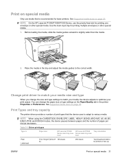
...type settings on the Paper/Quality tab in the tray and adjust the media guides to be printed on face up. NOTE: On the HP LaserJet P1006/P1009/P1500 Series, use media that the device uses to adapt to various media. You can change the size and type settings to match... on page 23. Table 5-1 Driver print types Type is recommended for printing multiple envelopes or other special media. Use the main input tray for laser printers. ENWW Print on special media Only use the priority feed slot for printing one envelope or other special media. 1. NOTE: When using the CARDSTOCK...
...type settings on the Paper/Quality tab in the tray and adjust the media guides to be printed on face up. NOTE: On the HP LaserJet P1006/P1009/P1500 Series, use media that the device uses to adapt to various media. You can change the size and type settings to match... on page 23. Table 5-1 Driver print types Type is recommended for printing multiple envelopes or other special media. Use the main input tray for laser printers. ENWW Print on special media Only use the priority feed slot for printing one envelope or other special media. 1. NOTE: When using the CARDSTOCK...
Service Guide
Page 11
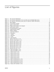
List of figures Figure 1-1 HP LaserJet P1000 Series ...2 Figure 1-2 HP LaserJet P1000 Series, front view (HP LaserJet P1006/P1008 shown 4 Figure 1-3 HP LaserJet P1000 Series, back view (HP LaserJet P1006/P1008 shown 4 Figure 3-1 Block diagram ...26 Figure 3-2 Cross-section of printer ...27 Figure 3-3 Engine control system ...29 Figure 3-4 Engine control system circuit diagram 30 Figure 3-5 Laser/scanner system ...31 Figure 3-6 Pickup/feed/delivery system ...32...
List of figures Figure 1-1 HP LaserJet P1000 Series ...2 Figure 1-2 HP LaserJet P1000 Series, front view (HP LaserJet P1006/P1008 shown 4 Figure 1-3 HP LaserJet P1000 Series, back view (HP LaserJet P1006/P1008 shown 4 Figure 3-1 Block diagram ...26 Figure 3-2 Cross-section of printer ...27 Figure 3-3 Engine control system ...29 Figure 3-4 Engine control system circuit diagram 30 Figure 3-5 Laser/scanner system ...31 Figure 3-6 Pickup/feed/delivery system ...32...
Service Guide
Page 39
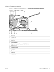
Internal components Figure 3-2 Cross-section of printer 1 2 3 4 5 6 12 11 10 9 8 7 1 Fusing unit 2 Pressure roller 3 Delivery roller 4 Fusing film 5 Laser/scanner unit 6 Single-sheet-feed slot (HP LaserJet P1006/P1008 only) 7 Multi-purpose tray 8 Photosensitive drum 9 Pickup roller 10 Separation pad 11 Feed roller 12 Transfer roller ENWW Internal components 27 Figure 3-2 Cross-section of printer on page 27 highlights the major internal components.
Internal components Figure 3-2 Cross-section of printer 1 2 3 4 5 6 12 11 10 9 8 7 1 Fusing unit 2 Pressure roller 3 Delivery roller 4 Fusing film 5 Laser/scanner unit 6 Single-sheet-feed slot (HP LaserJet P1006/P1008 only) 7 Multi-purpose tray 8 Photosensitive drum 9 Pickup roller 10 Separation pad 11 Feed roller 12 Transfer roller ENWW Internal components 27 Figure 3-2 Cross-section of printer on page 27 highlights the major internal components.


