HP LaserJet 5000, 5000 N, 5000 GN, and 5000 DN Printers - User Guide
Page 90
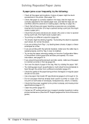
..., and meets printer specifications (page A-17). • Clean the printer (page 67). • Contact an HP-authorized service or support provider to perform routine printer maintenance. (See the HP Support pages at a time. • If you are printing small sizes (such as perforated or multi-sheet ... HP specifications (pages A-2 through the printer from the Configuration Menu in the printer's control panel (this will slow print speed). A piece of paper or fewer envelopes at the front of paper in a printer or copier. (Do not print on page 30.) • Check that the power supplied to...
..., and meets printer specifications (page A-17). • Clean the printer (page 67). • Contact an HP-authorized service or support provider to perform routine printer maintenance. (See the HP Support pages at a time. • If you are printing small sizes (such as perforated or multi-sheet ... HP specifications (pages A-2 through the printer from the Configuration Menu in the printer's control panel (this will slow print speed). A piece of paper or fewer envelopes at the front of paper in a printer or copier. (Do not print on page 30.) • Check that the power supplied to...

HP LaserJet 5000, 5000 N, 5000 GN, and 5000 DN Printers - User Guide
Page 103
... through the available languages. The display shows garbled or unfamiliar characters. A message other than READY is in this user's guide, contact an HP-authorized service or support provider. (See the HP Support pages at the front of this user's guide.) Turn the printer off . Press [-Value+] to step 2. Press [Select] to see... after following the suggestions in the wrong language. Determining Printer Problems Troubleshooting Flowchart If the printer is selected from the control panel. Check that the power supplied to determine the problem.
... through the available languages. The display shows garbled or unfamiliar characters. A message other than READY is in this user's guide, contact an HP-authorized service or support provider. (See the HP Support pages at the front of this user's guide.) Turn the printer off . Press [-Value+] to step 2. Press [Select] to see... after following the suggestions in the wrong language. Determining Printer Problems Troubleshooting Flowchart If the printer is selected from the control panel. Check that the power supplied to determine the problem.

HP LaserJet 5000, 5000 N, 5000 GN, and 5000 DN Printers - User Guide
Page 106
... Print speed is not taking effect. To test, try a different file. Check that you solve the problem. You might be missing a printer message that the power supplied to the printer (page C-1). From the Configuration Menu in the middle of the page prints. Simplify the print job. Check settings in the printer's control...
... Print speed is not taking effect. To test, try a different file. Check that you solve the problem. You might be missing a printer message that the power supplied to the printer (page C-1). From the Configuration Menu in the middle of the page prints. Simplify the print job. Check settings in the printer's control...

HP LaserJet 5000, 5000 N, and 5000 GN Printers - Getting Started Guide
Page 9
Location requirements for the printer • A sturdy, level surface for placement • Space allowance around the printer • Adequate power supply • A stable environment-no abrupt temperature or humidity changes • A well ventilated room • No exposure to direct sunlight or chemicals, including ammonia based cleaning solutions • Relative humidity 20% to 80% • Room temperature 50° to 91° F (15° to 32.5° C) 6 Getting Started Guide EN
Location requirements for the printer • A sturdy, level surface for placement • Space allowance around the printer • Adequate power supply • A stable environment-no abrupt temperature or humidity changes • A well ventilated room • No exposure to direct sunlight or chemicals, including ammonia based cleaning solutions • Relative humidity 20% to 80% • Room temperature 50° to 91° F (15° to 32.5° C) 6 Getting Started Guide EN

HP LaserJet 5000, 5000 N, and 5000 GN Printers - Quick Reference Guide
Page 25
...) to perform routine printer maintenance. (See the HP Support pages at the front of paper in a printer or copier. (Do not print on both sides of envelopes, transparencies, vellum, or labels.) • Check that the power supplied to the printer is steady, and meets printer ...specifications. • Clean the printer. • Contact an HP-authorized service or support provider to feed through the printer from a different orientation. •...
...) to perform routine printer maintenance. (See the HP Support pages at the front of paper in a printer or copier. (Do not print on both sides of envelopes, transparencies, vellum, or labels.) • Check that the power supplied to the printer is steady, and meets printer ...specifications. • Clean the printer. • Contact an HP-authorized service or support provider to feed through the printer from a different orientation. •...

Service Manual
Page 6
5 Functional Information Overview 5-1 Printer Subsystems 5-2 Power Supply System 5-3 AC/DC Power Distribution 5-3 Overcurrent Overvoltage Protection 5-5 High Voltage Power Distribution 5-6 Toner Cartridge Detection 5-7 DC Controller System 5-7 Laser and Scanner Drive 5-8 Paper Motion Monitoring and Control 5-9 Solenoids, Sensors, Clutches, and Switches 5-9 Engine Test Print 5-9 Motors 5-...
5 Functional Information Overview 5-1 Printer Subsystems 5-2 Power Supply System 5-3 AC/DC Power Distribution 5-3 Overcurrent Overvoltage Protection 5-5 High Voltage Power Distribution 5-6 Toner Cartridge Detection 5-7 DC Controller System 5-7 Laser and Scanner Drive 5-8 Paper Motion Monitoring and Control 5-9 Solenoids, Sensors, Clutches, and Switches 5-9 Engine Test Print 5-9 Motors 5-...
Service Manual
Page 7
... Pickup Solenoid 6-39 Fan 6-40 Formatter Assembly 6-41 Tray 1 Roller 6-42 Tray 2 Roller 6-43 Paper Feed Roller Assembly 6-44 DC Controller Board and Power Supply 6-47 Paper Feed Belt Assembly 6-51 Tray 1 Shaft 6-53 Tray 2 Shaft 6-55 Tray 1 Lift Plate 6-57 Tray 1 Separation Pad 6-58 Paper... Guide 6-59 Paper Path Detect Sensor 6-60 Face Down Bin Full Sensor 6-61 Power Connection 6-63 Registration Assembly 6-64 Upper Delivery Assembly 6-66 Delivery Roller Removal 6-68 Laser Scanner Assembly 6-70 Main Motor 6-71 Toner Cartridge Guides...
... Pickup Solenoid 6-39 Fan 6-40 Formatter Assembly 6-41 Tray 1 Roller 6-42 Tray 2 Roller 6-43 Paper Feed Roller Assembly 6-44 DC Controller Board and Power Supply 6-47 Paper Feed Belt Assembly 6-51 Tray 1 Shaft 6-53 Tray 2 Shaft 6-55 Tray 1 Lift Plate 6-57 Tray 1 Separation Pad 6-58 Paper... Guide 6-59 Paper Path Detect Sensor 6-60 Face Down Bin Full Sensor 6-61 Power Connection 6-63 Registration Assembly 6-64 Upper Delivery Assembly 6-66 Delivery Roller Removal 6-68 Laser Scanner Assembly 6-70 Main Motor 6-71 Toner Cartridge Guides...
Service Manual
Page 92
5 Functional Information Overview This chapter discusses the following: q Power Supply Subsystem q DC Controller Subsystem q Formatter PCA q Control Panel q Interface PCA q Image Formation System q Paper Feed System q Basic Sequence of Operation EN Overview 5-1
5 Functional Information Overview This chapter discusses the following: q Power Supply Subsystem q DC Controller Subsystem q Formatter PCA q Control Panel q Interface PCA q Image Formation System q Paper Feed System q Basic Sequence of Operation EN Overview 5-1

Service Manual
Page 94
EN Power Supply System 5-3 The low-voltage power supply divides the AC voltage to +24 VDC, +5 VDC and +3.4 VDC and supplies them to the low-voltage power supply circuit through the fuse (FU1). This circuit generates a zero-cross signal (ZEROX) and supplies it to the DC controller PCA. +3.4 VDC is supplied to ICs on the DC... controller PCA and the BD PCA. +5 VDC is supplied to the laser driver PCA and sensors. +24 VDC is supplied to the high-voltage power supply PCA to drive the main motor, the exhaust fan, the scanner motor, the clutches, and the solenoids. +24 VDC is ...
EN Power Supply System 5-3 The low-voltage power supply divides the AC voltage to +24 VDC, +5 VDC and +3.4 VDC and supplies them to the low-voltage power supply circuit through the fuse (FU1). This circuit generates a zero-cross signal (ZEROX) and supplies it to the DC controller PCA. +3.4 VDC is supplied to ICs on the DC... controller PCA and the BD PCA. +5 VDC is supplied to the laser driver PCA and sensors. +24 VDC is supplied to the high-voltage power supply PCA to drive the main motor, the exhaust fan, the scanner motor, the clutches, and the solenoids. +24 VDC is ...

Service Manual
Page 95
If an excess-current or excess-voltage protection system is activated and the power supply circuit does not output DC voltage, it is necessary to protect the power supplies. The circuit has two fuses which break and cut off , correct the problem in the faulty load, then turn the printer ...on again. Figure 5-2 Low Voltage Power Supply Circuit If a short circuit or other problems on the load side cause an excessive current flow from the +24 VDC or +3.4 VDC power supplies or generate abnormal voltage, the excess-current protection system and excess-voltage ...
If an excess-current or excess-voltage protection system is activated and the power supply circuit does not output DC voltage, it is necessary to protect the power supplies. The circuit has two fuses which break and cut off , correct the problem in the faulty load, then turn the printer ...on again. Figure 5-2 Low Voltage Power Supply Circuit If a short circuit or other problems on the load side cause an excessive current flow from the +24 VDC or +3.4 VDC power supplies or generate abnormal voltage, the excess-current protection system and excess-voltage ...

Service Manual
Page 96
... Overcurrent Overvoltage Protection This circuit located on the DC controller PCA always monitors an abnormal rise of the comparator (IC304) goes "L." EN Power Supply System 5-5 When the fusing roller heater temperature rises and the output voltage of the thermistor exceeds about 0.6 V (220°C), the ...safety circuit in the fusing roller heater interrupts the power to the Formatter. q The CPU monitors the thermistor (TH1301) voltage. q If the fusing roller heater temperature rises excessively and the ...
... Overcurrent Overvoltage Protection This circuit located on the DC controller PCA always monitors an abnormal rise of the comparator (IC304) goes "L." EN Power Supply System 5-5 When the fusing roller heater temperature rises and the output voltage of the thermistor exceeds about 0.6 V (220°C), the ...safety circuit in the fusing roller heater interrupts the power to the Formatter. q The CPU monitors the thermistor (TH1301) voltage. q If the fusing roller heater temperature rises excessively and the ...
Service Manual
Page 97
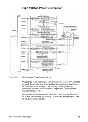
According to the image density information sent from the microprocessor (CPU: IC301) on the DC controller, this circuit varies the primary DC bias and developing DC bias to the transfer charging roller. High Voltage Power Distribution Figure 5-3 High Voltage Power Supply Circuit In response to the instructions from the Formatter PCA, this circuit applies the superimposed voltage of DC voltage and AC voltage to the primary charging roller and developing cylinder, and a positive or negative DC voltage to adjust the image density. 5-6 Functional Information EN
According to the image density information sent from the microprocessor (CPU: IC301) on the DC controller, this circuit varies the primary DC bias and developing DC bias to the transfer charging roller. High Voltage Power Distribution Figure 5-3 High Voltage Power Supply Circuit In response to the instructions from the Formatter PCA, this circuit applies the superimposed voltage of DC voltage and AC voltage to the primary charging roller and developing cylinder, and a positive or negative DC voltage to adjust the image density. 5-6 Functional Information EN

Service Manual
Page 98
...the toner detection signal. The presence of the developing AC bias and the output value (ANT) from the external device. EN Power Supply System 5-7 The CPU detects the remaining toner level and the presence of this circuit. DC Controller System The following systems and ...functions are controlled by the DC Controller PCA: q DC Power Distribution (+3.4 VDC, +5 VDC, +24 VA) q Laser and Scanner Drive q Paper Motion Monitoring and Control (photosensors and flags) q Clutches (tray...
...the toner detection signal. The presence of the developing AC bias and the output value (ANT) from the external device. EN Power Supply System 5-7 The CPU detects the remaining toner level and the presence of this circuit. DC Controller System The following systems and ...functions are controlled by the DC Controller PCA: q DC Power Distribution (+3.4 VDC, +5 VDC, +24 VA) q Laser and Scanner Drive q Paper Motion Monitoring and Control (photosensors and flags) q Clutches (tray...
Service Manual
Page 100
Paper Motion Monitoring and Control The DC Controller Board controls paper motion by continuously monitoring the various paper sensors, and coordinating paper movement with the other print processes. EN Power Supply System 5-9 For more information, see "Paper Feed System" on page 7-107. Solenoids, Sensors, Clutches, and Switches See "DC Controller PCA Inputs and Outputs" on page 5-29. Engine Test Print See "Engine Test" on page 7-9.
Paper Motion Monitoring and Control The DC Controller Board controls paper motion by continuously monitoring the various paper sensors, and coordinating paper movement with the other print processes. EN Power Supply System 5-9 For more information, see "Paper Feed System" on page 7-107. Solenoids, Sensors, Clutches, and Switches See "DC Controller PCA Inputs and Outputs" on page 5-29. Engine Test Print See "Engine Test" on page 7-9.

Service Manual
Page 102
... 99 (/HALFFAN) "H" and runs the fan motor half a turn. If the printing ends, the fan motor is run the fan motor at half speed. EN Power Supply System 5-11 The CPU controls the half-speed/full-speed rotations according to run at full speed for 30 seconds after the main motor stops...
... 99 (/HALFFAN) "H" and runs the fan motor half a turn. If the printing ends, the fan motor is run the fan motor at half speed. EN Power Supply System 5-11 The CPU controls the half-speed/full-speed rotations according to run at full speed for 30 seconds after the main motor stops...

Service Manual
Page 185
...-tapping screws (B) are located on the left side of the chassis (Figure 6-37). One houses the DC Controller and the High-Voltage Power Supply, and the other contains the LowVoltage Power Supply. 1 Remove the Top Cover (page 6-12), Left and Right Side Covers (page 6-23), and the Formatter Assembly (page 6-40). 2...use a flatblade screwdriver to release the locks by pressing down on the tabs on the back side of the chassis. DC Controller Board and Power Supply This assembly contains two PCAs. Be sure to pull the cables away from the chassis. 4 Remove five screws on top of the DC ...
...-tapping screws (B) are located on the left side of the chassis (Figure 6-37). One houses the DC Controller and the High-Voltage Power Supply, and the other contains the LowVoltage Power Supply. 1 Remove the Top Cover (page 6-12), Left and Right Side Covers (page 6-23), and the Formatter Assembly (page 6-40). 2...use a flatblade screwdriver to release the locks by pressing down on the tabs on the back side of the chassis. DC Controller Board and Power Supply This assembly contains two PCAs. Be sure to pull the cables away from the chassis. 4 Remove five screws on top of the DC ...

Service Manual
Page 188
Figure 6-39 DC Controller Assembly Hint Item A B C Explanation Power Supply PCA Ribbon Cable DC Controller PCA To prevent damage to the high voltage contacts, the Paper Feed Belt Assembly needs to remove. Carefully remove the ribbon cable that connects them, and loosen the screws on the board you wish to be installed before the DC Controller is reinstalled. EN Removing Assemblies 6-49 8 The boards are linked by a ribbon cable and held onto the tray with four screws each.
Figure 6-39 DC Controller Assembly Hint Item A B C Explanation Power Supply PCA Ribbon Cable DC Controller PCA To prevent damage to the high voltage contacts, the Paper Feed Belt Assembly needs to remove. Carefully remove the ribbon cable that connects them, and loosen the screws on the board you wish to be installed before the DC Controller is reinstalled. EN Removing Assemblies 6-49 8 The boards are linked by a ribbon cable and held onto the tray with four screws each.

Service Manual
Page 223
...a systematic approach that addresses the major problems first, then other problems as you identify the causes for Troubleshooting Power On (page 7-7) Does the printer perform the initialization and power-on page 7-4 illustrates the major steps for clearing Control Panel error messages and displaying and correcting Event Log codes... the Event Log? Information Pages (page 7-43) Will the printer print information pages successfully? This section gives the procedures for correcting power supply problems. Display (page 7-11) Does the Control Panel indicate READY, OFFLINE, or POWERSAVE ON?
...a systematic approach that addresses the major problems first, then other problems as you identify the causes for Troubleshooting Power On (page 7-7) Does the printer perform the initialization and power-on page 7-4 illustrates the major steps for clearing Control Panel error messages and displaying and correcting Event Log codes... the Event Log? Information Pages (page 7-43) Will the printer print information pages successfully? This section gives the procedures for correcting power supply problems. Display (page 7-11) Does the Control Panel indicate READY, OFFLINE, or POWERSAVE ON?

Service Manual
Page 228
..., perform the following : 1. Replace the Control Panel assembly. EN Troubleshooting the Printing System 7-7 Power On It is important to the on position. Is AC and DC power available? DC power supply is blank: 1. Disconnect all the printer's paper handling options. 2. See "Engine Test" on...as soon as the rocker switch is toggled. the printer's Engine Controller Board. If the Fan is not successful, replace the Power Supply. Print an engine test. Replace the Formatter. An operational Fan indicates the following steps: a. d. Reseat the Control Panel ...
..., perform the following : 1. Replace the Control Panel assembly. EN Troubleshooting the Printing System 7-7 Power On It is important to the on position. Is AC and DC power available? DC power supply is blank: 1. Disconnect all the printer's paper handling options. 2. See "Engine Test" on...as soon as the rocker switch is toggled. the printer's Engine Controller Board. If the Fan is not successful, replace the Power Supply. Print an engine test. Replace the Formatter. An operational Fan indicates the following steps: a. d. Reseat the Control Panel ...

Service Manual
Page 229
... is not firmly plugged into another AC circuit outlet. Blown fuse. 1. Defective power switch. Otherwise, replace the Power Supply. Check the fuse (F1) on the Power Supply. 2. Check the printer's AC receptacle and wiring for the AC power line. printer and the outlet. The power cord is found, replace the Power Supply. 7-8 Troubleshooting EN Defective AC receptacle or AC...
... is not firmly plugged into another AC circuit outlet. Blown fuse. 1. Defective power switch. Otherwise, replace the Power Supply. Check the fuse (F1) on the Power Supply. 2. Check the printer's AC receptacle and wiring for the AC power line. printer and the outlet. The power cord is found, replace the Power Supply. 7-8 Troubleshooting EN Defective AC receptacle or AC...

