Packer Arm Installation
Page 1
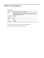
... document is accurate at the date of this document. Document number CA393-00540 Revision number Rev03 Kit number Q5025C Date 17 July 2018 Security level HP Confidential The information contained in the rewinder Scope HP Indigo WS6000 Digital Press, HP Indigo WS6600 Digital Press, HP Indigo WS6800 Digital Press, HP Indigo 6900 Digital Press, HP Indigo 6r Digital Press, HP Indigo 8000 Digital Press, HP Indigo press ws4500, HP Indigo WS4600 Digital Press. Check CE Suitcase for the most recent version of release.
... document is accurate at the date of this document. Document number CA393-00540 Revision number Rev03 Kit number Q5025C Date 17 July 2018 Security level HP Confidential The information contained in the rewinder Scope HP Indigo WS6000 Digital Press, HP Indigo WS6600 Digital Press, HP Indigo WS6800 Digital Press, HP Indigo 6900 Digital Press, HP Indigo 6r Digital Press, HP Indigo 8000 Digital Press, HP Indigo press ws4500, HP Indigo WS4600 Digital Press. Check CE Suitcase for the most recent version of release.
Packer Arm Installation
Page 6
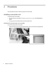
Remove the three screws securing the shipping bracket. 2 Procedures This topic explains the steps to the rewinder cabinet, remove the cabinet doors. Installing the internal packer arm assembly To install the internal packer arm assembly: 1. Bookmark not defined.. ● For easy access to install a new packer arm in the rewinder Installing a new packer arm To install the packer arm assembly: ● Shut down the press as described in "Installing a new packer arm on page 4" Error! Remove and discard the shipping bracket 4 Chapter 2 Procedures
Remove the three screws securing the shipping bracket. 2 Procedures This topic explains the steps to the rewinder cabinet, remove the cabinet doors. Installing the internal packer arm assembly To install the internal packer arm assembly: 1. Bookmark not defined.. ● For easy access to install a new packer arm in the rewinder Installing a new packer arm To install the packer arm assembly: ● Shut down the press as described in "Installing a new packer arm on page 4" Error! Remove and discard the shipping bracket 4 Chapter 2 Procedures
Packer Arm Installation
Page 29
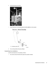
6. Turn on the pressStart the press software. Mount the packer arm threading label (p/n CA396-00880) onto the rewinder. 8. Set the air pressure to ensure that the lower packer arm cylinder is leveled. Completing the installation Level the external packer arm assembly, as follows: 1. Use a level to 0.2 bars. 7. Completing the installation 27
6. Turn on the pressStart the press software. Mount the packer arm threading label (p/n CA396-00880) onto the rewinder. 8. Set the air pressure to ensure that the lower packer arm cylinder is leveled. Completing the installation Level the external packer arm assembly, as follows: 1. Use a level to 0.2 bars. 7. Completing the installation 27
Packer Arm Installation
Page 31
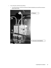
Completing the installation 29 Turn on the press. Start the press software. ● To set the air pressure, open the securing nut. 5. Rotate the adjusting screw until the air pressure gauge reads 0.2 bars.
Completing the installation 29 Turn on the press. Start the press software. ● To set the air pressure, open the securing nut. 5. Rotate the adjusting screw until the air pressure gauge reads 0.2 bars.
Packer Arm Installation
Page 32
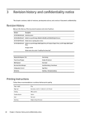
...a notice of authors. Revision Description CA393-00540 Rev00 Initial document CA393-00540 Rev01 Added to scope HP Indigo WS6600, WS6800 and WS4600 Digital Presses CA393-00540 Rev02 Added note on opening piston valves CA393-00540 Rev03 Added to achieve the best print...Kopel Yuval Bloomberg / Isaac Diwan Sigal Aknin Chip Moss / Yehudah Goldberg Printing instructions Follow these recommendations to scope HP Indigo 6900 Digital Press, HP Indigo 6r Digital Press, and HP Indigo 8000 Digital Press. Paper weight Page size Printing Simplex/duplex Color Finishing 80 g A4, Letter, or 8.27 x 11....
...a notice of authors. Revision Description CA393-00540 Rev00 Initial document CA393-00540 Rev01 Added to scope HP Indigo WS6600, WS6800 and WS4600 Digital Presses CA393-00540 Rev02 Added note on opening piston valves CA393-00540 Rev03 Added to achieve the best print...Kopel Yuval Bloomberg / Isaac Diwan Sigal Aknin Chip Moss / Yehudah Goldberg Printing instructions Follow these recommendations to scope HP Indigo 6900 Digital Press, HP Indigo 6r Digital Press, and HP Indigo 8000 Digital Press. Paper weight Page size Printing Simplex/duplex Color Finishing 80 g A4, Letter, or 8.27 x 11....
Rewinder Service
Page 1
i Check CE Suitcase for the most recent version of this document is accurate at the date of release. Document number CA393-00580 Revision number Rev 04 Date 16 November 2021 Security level HP Confidential The information contained in this document. Rewinder Service Document details Purpose To describe how to service the rewinder Scope HP Indigo WS6000 Digital Press, HP Indigo WS6600 Digital Press, HP Indigo WS6800 Digital Press, HP Indigo WS4500 Digital Press, HP Indigo WS4600 Digital Press.
i Check CE Suitcase for the most recent version of this document is accurate at the date of release. Document number CA393-00580 Revision number Rev 04 Date 16 November 2021 Security level HP Confidential The information contained in this document. Rewinder Service Document details Purpose To describe how to service the rewinder Scope HP Indigo WS6000 Digital Press, HP Indigo WS6600 Digital Press, HP Indigo WS6800 Digital Press, HP Indigo WS4500 Digital Press, HP Indigo WS4600 Digital Press.
Rewinder Service
Page 6
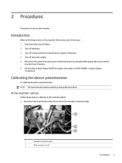
... all sources of electrical power by using the Main Supply Disconnect switch mounted near the press. 6. Lockout-Tagout Procedures). Introduction When performing service on the rewinder connector plate. 1 Rewinder connector's plate 2 Molex connector at J43 ... cabinet Follow these steps to CA493-00080 - Calibrating the dancer potentiometer To calibrate the dancer potentiometer: NOTE: The press should remain powered up during this procedure. Shut down the press software. 2. Perform the Lockout-Tagout (LOTO) procedure (according to calibrate at the rewinder cabinet. ● Disconnect...
... all sources of electrical power by using the Main Supply Disconnect switch mounted near the press. 6. Lockout-Tagout Procedures). Introduction When performing service on the rewinder connector plate. 1 Rewinder connector's plate 2 Molex connector at J43 ... cabinet Follow these steps to CA493-00080 - Calibrating the dancer potentiometer To calibrate the dancer potentiometer: NOTE: The press should remain powered up during this procedure. Shut down the press software. 2. Perform the Lockout-Tagout (LOTO) procedure (according to calibrate at the rewinder cabinet. ● Disconnect...
Rewinder Service
Page 10
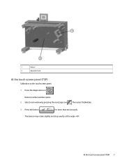
Select next window by pressing the next page icon . Press the button for more than two seconds. The dancer may rotate slightly and stop exactly at the touch screen panel. 1. 1 Dancer 2 Rewinder front At the touch screen panel (TSP) Calibration at the angle -40°. At the touch screen panel (TSP) 7 Dancer position window opens. 2. Then select Technician. 3. Press the diagnostic icon .
Select next window by pressing the next page icon . Press the button for more than two seconds. The dancer may rotate slightly and stop exactly at the touch screen panel. 1. 1 Dancer 2 Rewinder front At the touch screen panel (TSP) Calibration at the angle -40°. At the touch screen panel (TSP) 7 Dancer position window opens. 2. Then select Technician. 3. Press the diagnostic icon .
Rewinder Service
Page 11
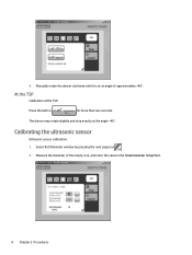
Press the button for more than two seconds. Select Roll Diameter window by pressing the next page icon . 2. 4. Measure the diameter of approximately +40°. The dancer may rotate slightly and stop exactly at the TSP. At the TSP Calibration at the angle +40°. Manually rotate the dancer clockwise until it is at an angle of the empty core, and enter the value in the Small diameter Setup field. 8 Chapter 2 Procedures Calibrating the ultrasonic sensor Ultrasonic sensor calibration. 1.
Press the button for more than two seconds. Select Roll Diameter window by pressing the next page icon . 2. 4. Measure the diameter of approximately +40°. The dancer may rotate slightly and stop exactly at the TSP. At the TSP Calibration at the angle +40°. Manually rotate the dancer clockwise until it is at an angle of the empty core, and enter the value in the Small diameter Setup field. 8 Chapter 2 Procedures Calibrating the ultrasonic sensor Ultrasonic sensor calibration. 1.
Rewinder Service
Page 12
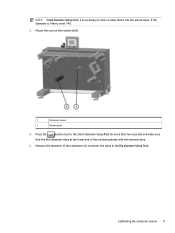
Calibrating the ultrasonic sensor 9 Press the button next to enter a value that the Roll diameter value at the lower end of the substrate roll, and enter the value in the Big diameter Setup field. Mount the core on the rewind shaft. 1 Ultrasonic sensor 2 Rewind shaft 4. Measure the diameter of the window updates with the entered value. 5. If the diameter is 10x the actual value. NOTE: Small diameter Setup field, it is necessary to the Small diameter Setup field for more than two seconds and make sure that is 74mm, enter 740. 3.
Calibrating the ultrasonic sensor 9 Press the button next to enter a value that the Roll diameter value at the lower end of the substrate roll, and enter the value in the Big diameter Setup field. Mount the core on the rewind shaft. 1 Ultrasonic sensor 2 Rewind shaft 4. Measure the diameter of the window updates with the entered value. 5. If the diameter is 10x the actual value. NOTE: Small diameter Setup field, it is necessary to the Small diameter Setup field for more than two seconds and make sure that is 74mm, enter 740. 3.
Rewinder Service
Page 13
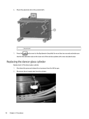
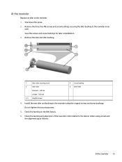
Mount the substrate roll on the unwind shaft. 1 Unwind shaft 7. Replacing the dancer glass cylinder Replacement of the window updates with a new calculated value. Shut down the press and release the air pressure from the cylinder. 10 Chapter 2 Procedures Press the button next to the Big diameter Setup field for more than two seconds and make sure that the Roll diameter value at the lower end of the dancer glass cylinder. 1. Disconnect the air supply tube from the UW air gun. 2. 6.
Mount the substrate roll on the unwind shaft. 1 Unwind shaft 7. Replacing the dancer glass cylinder Replacement of the window updates with a new calculated value. Shut down the press and release the air pressure from the cylinder. 10 Chapter 2 Procedures Press the button next to the Big diameter Setup field for more than two seconds and make sure that the Roll diameter value at the lower end of the dancer glass cylinder. 1. Disconnect the air supply tube from the UW air gun. 2. 6.
Rewinder Service
Page 14
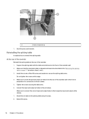
... page 3". 2. Shut down the press as described in order to gain access to To remove the splicing table: 1. Install the new glass cylinder using the original two screws. 5. Connect the ...
... page 3". 2. Shut down the press as described in order to gain access to To remove the splicing table: 1. Install the new glass cylinder using the original two screws. 5. Connect the ...
Rewinder Service
Page 16
... 3, 5 Hex M6 screws 4 Screw bushing 6 Idler shaft 4. Do not tighten the securing screws. 5. Save the screws and screw bushings for later reinstallation. 3. Shut down the press. 2. Check the leveling on the RW chassis. 6.
... 3, 5 Hex M6 screws 4 Screw bushing 6 Idler shaft 4. Do not tighten the securing screws. 5. Save the screws and screw bushings for later reinstallation. 3. Shut down the press. 2. Check the leveling on the RW chassis. 6.
Rewinder Service
Page 18
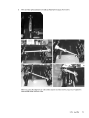
At the rewinder 15 d. Otherwise, place the alignment jig between the relevant rewinder and the press rollers to align the new rewinder roller as shown below . If the rewinder splicing table is removed, use the alignment jig as shown below .
At the rewinder 15 d. Otherwise, place the alignment jig between the relevant rewinder and the press rollers to align the new rewinder roller as shown below . If the rewinder splicing table is removed, use the alignment jig as shown below .
Rewinder Service
Page 19
... six sets of the rewinder wall. 2. Connect the input and output air tubes to the splicing table using tie wraps. 8. Start the press and rewinder. Make sure that the pneumatic plate is released and lowered as described in preparation for connections to the front of Hex M6 screws... and washers to reinstall the splicing table. Restart the press. 16 Chapter 2 Procedures At the rear of the rewinder Reinstall the splicing table at the rear of alignment jig 7. and 6.. 3. Reinstalling...
... six sets of the rewinder wall. 2. Connect the input and output air tubes to the splicing table using tie wraps. 8. Start the press and rewinder. Make sure that the pneumatic plate is released and lowered as described in preparation for connections to the front of Hex M6 screws... and washers to reinstall the splicing table. Restart the press. 16 Chapter 2 Procedures At the rear of the rewinder Reinstall the splicing table at the rear of alignment jig 7. and 6.. 3. Reinstalling...
Rewinder Service
Page 20
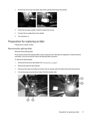
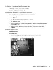
... follows: 1. Turn off or disconnect the compressed air supply to the press. 4. Perform the Lockout-Tagout (LOTO) procedure (according to replace the motor and/or motor gear. Lockout-Tagout Procedures). At the rewinder cabinet 1. Replacing the motor ... sources of electrical power by removing the two securing screws. Remove the motor gear guard by using the Main Supply Disconnect switch mounted near the press. 6. Replacing the motor and/or motor gear 17 Turn off the water supply. 5. Servo motor and gear kit P/N: CT990-00440 Preparation for replacing the motor...
... follows: 1. Turn off or disconnect the compressed air supply to the press. 4. Perform the Lockout-Tagout (LOTO) procedure (according to replace the motor and/or motor gear. Lockout-Tagout Procedures). At the rewinder cabinet 1. Replacing the motor ... sources of electrical power by removing the two securing screws. Remove the motor gear guard by using the Main Supply Disconnect switch mounted near the press. 6. Replacing the motor and/or motor gear 17 Turn off the water supply. 5. Servo motor and gear kit P/N: CT990-00440 Preparation for replacing the motor...
Rewinder Service
Page 23
Start the press. Servo motor and gear kit P/N: CT990-00440 NOTE: If the servo motor is replaced with an old version of the motor (CA345-18332), then there ...
Start the press. Servo motor and gear kit P/N: CT990-00440 NOTE: If the servo motor is replaced with an old version of the motor (CA345-18332), then there ...
Rewinder Service
Page 30
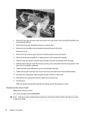
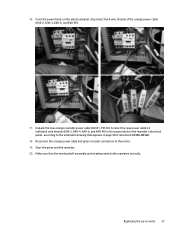
... the power block in page 40 of the orange power cable (K40-2, K40-4, K40-6, and K40-PE). 17. Replacing the servo motor 27 Start the press and the rewinder. 20. Make sure that appears in the rewinder's electrical panel, according to the motor. 19. From the power block on the electrical...
... the power block in page 40 of the orange power cable (K40-2, K40-4, K40-6, and K40-PE). 17. Replacing the servo motor 27 Start the press and the rewinder. 20. Make sure that appears in the rewinder's electrical panel, according to the motor. 19. From the power block on the electrical...
Rewinder Service
Page 31
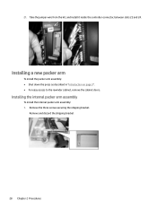
Remove the three screws securing the shipping bracket. Remove and discard the shipping bracket 28 Chapter 2 Procedures Take the jumper wire from the kit, and install it inside the controller connector, between slots 22 and 24. Installing a new packer arm To install the packer arm assembly: ● Shut down the press as described in "Introduction on page 3". ● For easy access to the rewinder cabinet, remove the cabinet doors. Installing the internal packer arm assembly To install the internal packer arm assembly: 1. 21.
Remove the three screws securing the shipping bracket. Remove and discard the shipping bracket 28 Chapter 2 Procedures Take the jumper wire from the kit, and install it inside the controller connector, between slots 22 and 24. Installing a new packer arm To install the packer arm assembly: ● Shut down the press as described in "Introduction on page 3". ● For easy access to the rewinder cabinet, remove the cabinet doors. Installing the internal packer arm assembly To install the internal packer arm assembly: 1. 21.
Rewinder Service
Page 57
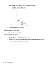
Mount the packer arm threading label (p/n CA396-00880) onto the rewinder. 8. Replacing the packer arm It explains the replacement of the packer arm. Remove the packer arm adjustable external assembly. 54 Chapter 2 Procedures Disassembling the packer arm Follow these steps to the packer arm fixed inner assembly. Turn on page 3" . 2. Shut down the press as described in "Introduction on the pressStart the press software. 7. Remove the 3 hex M8 screws securing the adjustable bushing to disassemble the packer arm. 1.
Mount the packer arm threading label (p/n CA396-00880) onto the rewinder. 8. Replacing the packer arm It explains the replacement of the packer arm. Remove the packer arm adjustable external assembly. 54 Chapter 2 Procedures Disassembling the packer arm Follow these steps to the packer arm fixed inner assembly. Turn on page 3" . 2. Shut down the press as described in "Introduction on the pressStart the press software. 7. Remove the 3 hex M8 screws securing the adjustable bushing to disassemble the packer arm. 1.


