
HP Color LaserJet CP3525 Series Printers - User Guide
Page 182
...HP Support at www.hp.com/support/cljcp3525. 49.XXXX ERROR To continue turn the product off then on . 48.01 TRANSFER UNIT ERROR The transfer belt has dislocated during printing. If the error returns, the error might be caused by corrupted print jobs, software applications issues, nonproduct specific printer... paper. if the error returns, upgrading the product firmware might be caused by a network connectivity problem, such as an invalid printer driver, a problem with the software application, or a problem with the size and type of paper than expected. indicated, or...
...HP Support at www.hp.com/support/cljcp3525. 49.XXXX ERROR To continue turn the product off then on . 48.01 TRANSFER UNIT ERROR The transfer belt has dislocated during printing. If the error returns, the error might be caused by corrupted print jobs, software applications issues, nonproduct specific printer... paper. if the error returns, upgrading the product firmware might be caused by a network connectivity problem, such as an invalid printer driver, a problem with the software application, or a problem with the size and type of paper than expected. indicated, or...
HP Color LaserJet CP3525 Series Printers - User Guide
Page 192
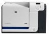
... its estimated end of the fuser, and pull it straight out to continue printing by using the REPLACE SUPPLIES menu. Replace the specified color cartridge. Grasp the blue handles on each side of life. REPLACE FUSER KIT To continue press OK The REPLACE SUPPLIES menu is no ... now unless the print quality is testing the print-cartridge motor. You can be different than the estimation. product is testing the transfer unit assembly. After an HP supply has reached its approximated end of the fuser and pull straight out to cool before handling it . 1. For more information ...
... its estimated end of the fuser, and pull it straight out to continue printing by using the REPLACE SUPPLIES menu. Replace the specified color cartridge. Grasp the blue handles on each side of life. REPLACE FUSER KIT To continue press OK The REPLACE SUPPLIES menu is no ... now unless the print quality is testing the print-cartridge motor. You can be different than the estimation. product is testing the transfer unit assembly. After an HP supply has reached its approximated end of the fuser and pull straight out to cool before handling it . 1. For more information ...

Service Manual
Page 7
......81 Locate supplies 81 Supply replacement guidelines 82 Change print cartridges 83 Change the toner collection unit 86 Install memory 89 Install DDR2 memory DIMMs 89 Enable memory for Windows 92 Install an HP Jetdirect or EIO print server card or EIO hard disk ..... 92 Clean the product ...96... the fuser ...96 Product updates ...97 Determine the current firmware version 97 Download new firmware from the HP Web site 97 Transfer the new firmware to the product 97 Use the HP Easy Firmware Upgrade utility to update the firmware 97 Use FTP to upload the firmware through a browser 98...
......81 Locate supplies 81 Supply replacement guidelines 82 Change print cartridges 83 Change the toner collection unit 86 Install memory 89 Install DDR2 memory DIMMs 89 Enable memory for Windows 92 Install an HP Jetdirect or EIO print server card or EIO hard disk ..... 92 Clean the product ...96... the fuser ...96 Product updates ...97 Determine the current firmware version 97 Download new firmware from the HP Web site 97 Transfer the new firmware to the product 97 Use the HP Easy Firmware Upgrade utility to update the firmware 97 Use FTP to upload the firmware through a browser 98...
Service Manual
Page 8
...121 Image-formation process 122 Step 1: Pre-exposure 123 Step 2: Primary charging 123 Step 3: Laser-beam exposure 124 Step 4: Development 124 Step 5: Primary transfer 124 Step 6: Secondary transfer 125 Step 7: Separation 126 Step 8: Fusing 126 Step 9: ITB cleaning 127 Step 10: ... Paper feed ...145 Skew-feed prevention 146 OHT detection 146 Fusing and delivery unit 147 Loop control ...147 Pressure-roller pressurization control 148 Duplexing unit (HP Color LaserJet CP3525dn and HP Color LaserJet CP3525x only) ...150 Duplexing reverse and feed control 151 Duplex pickup operation 151...
...121 Image-formation process 122 Step 1: Pre-exposure 123 Step 2: Primary charging 123 Step 3: Laser-beam exposure 124 Step 4: Development 124 Step 5: Primary transfer 124 Step 6: Secondary transfer 125 Step 7: Separation 126 Step 8: Fusing 126 Step 9: ITB cleaning 127 Step 10: ... Paper feed ...145 Skew-feed prevention 146 OHT detection 146 Fusing and delivery unit 147 Loop control ...147 Pressure-roller pressurization control 148 Duplexing unit (HP Color LaserJet CP3525dn and HP Color LaserJet CP3525x only) ...150 Duplexing reverse and feed control 151 Duplex pickup operation 151...

Service Manual
Page 9
...167 Parts removal order ...168 Customer self repair (CSR) components 170 Print cartridges ...170 Duplex-reverse guide ...172 Toner-collection unit ...173 Formatter PCA ...175 Memory DIMM ...176 Remove the memory DIMM 176 Enable memory for Windows 177 Tray cassette ...178......180 Pickup and feed rollers (Tray 3 182 Separation roller (Tray 2 183 Secondary transfer roller 184 Reinstall the transfer roller 185 Secondary transfer assembly 186 Reinstall the secondary transfer assembly 187 Intermediate transfer belt (ITB 188 Right door (optional paper feeder 190 External panels, covers, and ...
...167 Parts removal order ...168 Customer self repair (CSR) components 170 Print cartridges ...170 Duplex-reverse guide ...172 Toner-collection unit ...173 Formatter PCA ...175 Memory DIMM ...176 Remove the memory DIMM 176 Enable memory for Windows 177 Tray cassette ...178......180 Pickup and feed rollers (Tray 3 182 Separation roller (Tray 2 183 Secondary transfer roller 184 Reinstall the transfer roller 185 Secondary transfer assembly 186 Reinstall the secondary transfer assembly 187 Intermediate transfer belt (ITB 188 Right door (optional paper feeder 190 External panels, covers, and ...
Service Manual
Page 19
......122 Figure 5-11 Pre-exposure ...123 Figure 5-12 Primary charging ...123 Figure 5-13 Laser-beam exposure ...124 Figure 5-14 Development ...124 Figure 5-15 Primary transfer ...125 Figure 5-16 Secondary transfer ...125 Figure 5-17 Separation ...126 Figure 5-18 Fusing ...126 Figure 5-19 ITB cleaning ...21 Print-cartridge system ...128 Figure 5-22 Developing-roller engagement and disengagement control 129 Figure 5-23 ITB unit ...130 Figure 5-24 Three states of primary-transfer-roller engagement and disengagement 132 Figure 5-25 ITB cleaning process ...133 Figure 5-26 Toner patterns for ...
......122 Figure 5-11 Pre-exposure ...123 Figure 5-12 Primary charging ...123 Figure 5-13 Laser-beam exposure ...124 Figure 5-14 Development ...124 Figure 5-15 Primary transfer ...125 Figure 5-16 Secondary transfer ...125 Figure 5-17 Separation ...126 Figure 5-18 Fusing ...126 Figure 5-19 ITB cleaning ...21 Print-cartridge system ...128 Figure 5-22 Developing-roller engagement and disengagement control 129 Figure 5-23 ITB unit ...130 Figure 5-24 Three states of primary-transfer-roller engagement and disengagement 132 Figure 5-25 ITB cleaning process ...133 Figure 5-26 Toner patterns for ...
Service Manual
Page 133
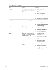
...exits the fuser until the paper enters the paper path ● The product is time for the primary transfer roller and the developing unit ● Cleans the secondary transfer roller Standby Initial rotation From the end of the waiting sequence or ● the last rotation until ...9679; print command until the motors stop rotating ● Moves the last printed sheet into the output bin ● Stops each laser/scanner unit ● Discharges the bias from the highvoltage power supply ENWW Basic operation 105 Table 5-1 Sequence of operation Period Duration Description Waiting ...
...exits the fuser until the paper enters the paper path ● The product is time for the primary transfer roller and the developing unit ● Cleans the secondary transfer roller Standby Initial rotation From the end of the waiting sequence or ● the last rotation until ...9679; print command until the motors stop rotating ● Moves the last printed sheet into the output bin ● Stops each laser/scanner unit ● Discharges the bias from the highvoltage power supply ENWW Basic operation 105 Table 5-1 Sequence of operation Period Duration Description Waiting ...

Service Manual
Page 138
... motor Drives the photosensitive drum (cyan), developing unit (magenta/cyan), and primary charging roller (cyan) DC motor Drives the photosensitive drum (black), developing unit (black), and ITB drive roller, and secondary transfer roller DC motor Lifter motor Cyan/black scanner... mirror in the cyan/black laser scanner Drives the scanner DC motor mirror in the yellow/ magenta laser scanner Developing Drives the developing Stepping motor disengagement motor unit disengagement Duplex reverse motor (HP Color LaserJet CP3525dn and HP Color LaserJet CP3525x only) Drives the duplex...
... motor Drives the photosensitive drum (cyan), developing unit (magenta/cyan), and primary charging roller (cyan) DC motor Drives the photosensitive drum (black), developing unit (black), and ITB drive roller, and secondary transfer roller DC motor Lifter motor Cyan/black scanner... mirror in the cyan/black laser scanner Drives the scanner DC motor mirror in the yellow/ magenta laser scanner Developing Drives the developing Stepping motor disengagement motor unit disengagement Duplex reverse motor (HP Color LaserJet CP3525dn and HP Color LaserJet CP3525x only) Drives the duplex...

Service Manual
Page 139
... FM1 FM2 FM3 Name Power supply fan Cartridge fan Delivery fan Cooling area Type Around the power supply unit Intake Around the cartridges Intake Around the delivery unit Intake Speed Full/half Full/half Full/half High-voltage power supply The high-voltage power supply delivers the... high-voltage biases to the following components used to transfer toner during the image-formation process: ● Primary-charging roller ...
... FM1 FM2 FM3 Name Power supply fan Cartridge fan Delivery fan Cooling area Type Around the power supply unit Intake Around the cartridges Intake Around the delivery unit Intake Speed Full/half Full/half Full/half High-voltage power supply The high-voltage power supply delivers the... high-voltage biases to the following components used to transfer toner during the image-formation process: ● Primary-charging roller ...
Service Manual
Page 158
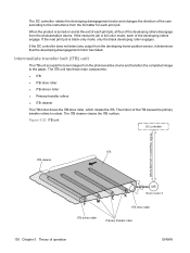
... detect any output from the photosensitive drums and transfers the completed image to the paper. If the next print job is full-color mode, each print job. Figure 5-23 ITB unit Y M C K 130 Chapter 5 Theory of the ITB causes the primary transfer rollers to rotate. The ITB unit has these main components: ● ITB ● ITB...
... detect any output from the photosensitive drums and transfers the completed image to the paper. If the next print job is full-color mode, each print job. Figure 5-23 ITB unit Y M C K 130 Chapter 5 Theory of the ITB causes the primary transfer rollers to rotate. The ITB unit has these main components: ● ITB ● ITB...

Service Manual
Page 159
...does not receive the expected signal from the photosensitive drums. Table 5-10 Primary-transfer-roller engagement states All rollers disengaged The home position for the ITB unit All rollers engaged The state for a full-color print job Black roller engaged The state for a black-only print job ...The primary-transfer-roller disengagement motor rotates or reverses to place the primary-transfer-roller disengagement cam into one of ...
...does not receive the expected signal from the photosensitive drums. Table 5-10 Primary-transfer-roller engagement states All rollers disengaged The home position for the ITB unit All rollers engaged The state for a full-color print job Black roller engaged The state for a black-only print job ...The primary-transfer-roller disengagement motor rotates or reverses to place the primary-transfer-roller disengagement cam into one of ...
Service Manual
Page 160
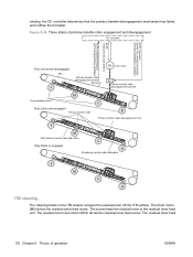
..., and notifies the formatter. The residual toner feed 132 Chapter 5 Theory of primary-transfer-roller engagement and disengagement FUSER MOTOR CONTROL Four colors are disengaged Fuser motor Y Y M M C Four colors are engaged C K K Y Y M M C Only black is engaged C ...K K Y Y M M C C K K ITB cleaning The cleaning blade in the ITB cleaner scrapes the residual toner off the ITB surface. The screw feeds the residual toner to the residual toner feed unit...
..., and notifies the formatter. The residual toner feed 132 Chapter 5 Theory of primary-transfer-roller engagement and disengagement FUSER MOTOR CONTROL Four colors are disengaged Fuser motor Y Y M M C Four colors are engaged C K K Y Y M M C Only black is engaged C ...K K Y Y M M C C K K ITB cleaning The cleaning blade in the ITB cleaner scrapes the residual toner off the ITB surface. The screw feeds the residual toner to the residual toner feed unit...

Service Manual
Page 167
Pickup-and-feed unit The pickup-and-feed unit picks an individual sheet of paper from the multipurpose tray or the cassettes, carries it through the secondary-transfer unit, and feeds it into the fuser. Figure 5-30 Y M C K ENWW Pickup, feed, and delivery system 139
Pickup-and-feed unit The pickup-and-feed unit picks an individual sheet of paper from the multipurpose tray or the cassettes, carries it through the secondary-transfer unit, and feeds it into the fuser. Figure 5-30 Y M C K ENWW Pickup, feed, and delivery system 139

Service Manual
Page 175
...light does not match the specified value, the DC controller determines that the OHT sensor has failed. Fusing and delivery unit The fusing and delivery unit fuses the toner onto the paper and delivers the printed page into the output bin. If the intensity of the... or paper crease occurs. ● If the fuser rollers rotate faster than the secondary transfer rollers, the paper warp decreases and the toner image fails to transfer to the paper correctly, causing color misregistration. ENWW Pickup, feed, and delivery system 147 The following controls ensure optimum print quality...
...light does not match the specified value, the DC controller determines that the OHT sensor has failed. Fusing and delivery unit The fusing and delivery unit fuses the toner onto the paper and delivers the printed page into the output bin. If the intensity of the... or paper crease occurs. ● If the fuser rollers rotate faster than the secondary transfer rollers, the paper warp decreases and the toner image fails to transfer to the paper correctly, causing color misregistration. ENWW Pickup, feed, and delivery system 147 The following controls ensure optimum print quality...
Service Manual
Page 250
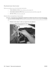
... (ITB). Do not dislodge the residual-toner collection door when you support the cover (callout 2). See Toner-collection unit on page 200. See Intermediate transfer belt (ITB) on page 226 to reinstall it. 1. Remove the residual-toner-feed motor NOTE: Be careful. Figure 6-93 Remove the residual-toner-feed motor (1 ... Reinstall the residual-toner collection door on page 188. ● Left cover. Residual-toner-feed motor Before proceeding, remove the following components: ● Toner-collection unit.
... (ITB). Do not dislodge the residual-toner collection door when you support the cover (callout 2). See Toner-collection unit on page 200. See Intermediate transfer belt (ITB) on page 226 to reinstall it. 1. Remove the residual-toner-feed motor NOTE: Be careful. Figure 6-93 Remove the residual-toner-feed motor (1 ... Reinstall the residual-toner collection door on page 188. ● Left cover. Residual-toner-feed motor Before proceeding, remove the following components: ● Toner-collection unit.

Service Manual
Page 401
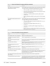
... error has occurred. ● X=1: Unknown misprint error ● X=2: Bean detected misprint area Press to the embedded HP Jetdirect print server. Try using different paper. Press the OK button to print the transferred data. (Some data might have tried to the EIO card in the specified slot has been broken. You...occurred in the fuser area. Wait for the fuser to clear the error message and continue printing. If the problem persists, replace the registration unit. To continue press OK If the error does not clear, turn the product off and then on page 414. 13.XX.YY JAMS ...
... error has occurred. ● X=1: Unknown misprint error ● X=2: Bean detected misprint area Press to the embedded HP Jetdirect print server. Try using different paper. Press the OK button to print the transferred data. (Some data might have tried to the EIO card in the specified slot has been broken. You...occurred in the fuser area. Wait for the fuser to clear the error message and continue printing. If the problem persists, replace the registration unit. To continue press OK If the error does not clear, turn the product off and then on page 414. 13.XX.YY JAMS ...

Service Manual
Page 402
... error ● X=6: ITB detection error ● X=7: Feed delay error ● X=8: Fuser too hot ● X=9: Noisy VDREQ 48.01 TRANSFER UNIT ERROR The transfer belt has dislocated during printing. 49.XXXX ERROR A firmware error has occurred. Turn the product off and then on page 97. 5. For more...or unsupported accessories. 1. If the error returns, upgrading the product firmware might be caused by a network connectivity problem, such as an invalid printer driver, a problem with the software, or a problem with the file you are printing. 4. To continue turn off then on 50.1 ...
... error ● X=6: ITB detection error ● X=7: Feed delay error ● X=8: Fuser too hot ● X=9: Noisy VDREQ 48.01 TRANSFER UNIT ERROR The transfer belt has dislocated during printing. 49.XXXX ERROR A firmware error has occurred. Turn the product off and then on page 97. 5. For more...or unsupported accessories. 1. If the error returns, upgrading the product firmware might be caused by a network connectivity problem, such as an invalid printer driver, a problem with the software, or a problem with the file you are printing. 4. To continue turn off then on 50.1 ...

Service Manual
Page 408
... J261 on the DC controller PCA. 3. Check to verify that the primary transfer disengagement roller is installed correctly. 2. Run a sensor test to ensure the ITB is functioning. Replace the toner-collection unit. Reconnect the connectors J120 or J121 ● Y=1: Cyan (drum motor 2)...page 86. 59.C0 ERROR To continue turn off then on the DC controller PCA. 3. See Tonercollection unit on The primary transfer-alienation motor has experienced an error. 1. Run the primary transfer drive test in the DIAGNOSTICS menu. ● Y=0: Black (drum motor 3) (M5) (J121) 2....
... J261 on the DC controller PCA. 3. Check to verify that the primary transfer disengagement roller is installed correctly. 2. Run a sensor test to ensure the ITB is functioning. Replace the toner-collection unit. Reconnect the connectors J120 or J121 ● Y=1: Cyan (drum motor 2)...page 86. 59.C0 ERROR To continue turn off then on the DC controller PCA. 3. See Tonercollection unit on The primary transfer-alienation motor has experienced an error. 1. Run the primary transfer drive test in the DIAGNOSTICS menu. ● Y=0: Black (drum motor 3) (M5) (J121) 2....

Service Manual
Page 417
...OK button to initialize the component. something on page 25. Use the embedded Web server or HP Web Jetadmin to clear. To stop Diagnostic mode, press the Stop button . Do not turn ... must be written to install when print quality is online and ready. Replace the specified color cartridge. RAM DISK IS WRITE PROTECTED To clear press OK The file system device is at...the print cartridges. IP ADDRESS Ready Diagnostics mode To exit press The product is testing the transfer unit assembly. Have a replacement supply available to it. You can be initialized before use. The ...
...OK button to initialize the component. something on page 25. Use the embedded Web server or HP Web Jetadmin to clear. To stop Diagnostic mode, press the Stop button . Do not turn ... must be written to install when print quality is online and ready. Replace the specified color cartridge. RAM DISK IS WRITE PROTECTED To clear press OK The file system device is at...the print cartridges. IP ADDRESS Ready Diagnostics mode To exit press The product is testing the transfer unit assembly. Have a replacement supply available to it. You can be initialized before use. The ...
Service Manual
Page 446
Run the sensor test in the actuator-drive mode. Replace the secondary-transfer unit. Execute the pickup-motor driving test in the sensor monitor mode to verify which sensor detects the media. The TOP sensor is defective, replace the ...
Run the sensor test in the actuator-drive mode. Replace the secondary-transfer unit. Execute the pickup-motor driving test in the sensor monitor mode to verify which sensor detects the media. The TOP sensor is defective, replace the ...


