
Service Manual
Page 7
...6-8 Solving Color Accuracy problems 6-9 Color Consistency problems 6-9 Long Term Color Bleeding (Glossy Papers) 6-9 Media 6-10 There are Smears or Scratching on the Printed Media 6-10 Parts and Diagrams 7-1 Printer Support 7-2 Right Hand Cover 7-4 Left Hand Cover 7-6 Top Cover and Deflectors 7-8 Rollfeed Module 7-10 Back Platen Assembly 7-12 Electronics Module 7-14 Power Supply 7-16 ... Platen Assembly 7-32 Carriage Assembly 7-34 Vacuum Fan 7-36 Interconnect Cable 7-38 Paper-Axis Motor 7-40 Drive Roller 7-42 Miscellaneous Items 7-44 HP DesignJets 500 and 800 Series Printers Service Manual 5
...6-8 Solving Color Accuracy problems 6-9 Color Consistency problems 6-9 Long Term Color Bleeding (Glossy Papers) 6-9 Media 6-10 There are Smears or Scratching on the Printed Media 6-10 Parts and Diagrams 7-1 Printer Support 7-2 Right Hand Cover 7-4 Left Hand Cover 7-6 Top Cover and Deflectors 7-8 Rollfeed Module 7-10 Back Platen Assembly 7-12 Electronics Module 7-14 Power Supply 7-16 ... Platen Assembly 7-32 Carriage Assembly 7-34 Vacuum Fan 7-36 Interconnect Cable 7-38 Paper-Axis Motor 7-40 Drive Roller 7-42 Miscellaneous Items 7-44 HP DesignJets 500 and 800 Series Printers Service Manual 5

Service Manual
Page 8
...13 Right End Roll-Feed 8-15 Back Platen 8-17 Media Sensor 8-19 Formatter 8-20 LAN Card 8-21 Spittoon 8-23 Electronics Module 8-24 Power Supply 8-27 Scan-Axis Motor Assembly 8-29 Cutter Assembly 8-32 Left Encoder Holder 8-33 Cutter Bushing 8-35 Cutter Guide Bracket 8-36 Drive Roller ...Supply Station 8-48 Interconnect PCA 8-50 Service Station and Aerosol Fan 8-52 Cutter Guide 8-55 Print Platen 8-56 Service Station Holder 8-57 Interconnect Cable 8-59 Ink Supply Tubes 8-60 Vacuum Fan 8-64 Pinch-Arm 8-66 Pinch-Arm Mechanism 8-67 Pinch-Arm Lever 8-69 6 HP DesignJets 500 and 800 Series Printers...
...13 Right End Roll-Feed 8-15 Back Platen 8-17 Media Sensor 8-19 Formatter 8-20 LAN Card 8-21 Spittoon 8-23 Electronics Module 8-24 Power Supply 8-27 Scan-Axis Motor Assembly 8-29 Cutter Assembly 8-32 Left Encoder Holder 8-33 Cutter Bushing 8-35 Cutter Guide Bracket 8-36 Drive Roller ...Supply Station 8-48 Interconnect PCA 8-50 Service Station and Aerosol Fan 8-52 Cutter Guide 8-55 Print Platen 8-56 Service Station Holder 8-57 Interconnect Cable 8-59 Ink Supply Tubes 8-60 Vacuum Fan 8-64 Pinch-Arm 8-66 Pinch-Arm Mechanism 8-67 Pinch-Arm Lever 8-69 6 HP DesignJets 500 and 800 Series Printers...

Service Manual
Page 9
... Maintenance 9-4 Functional Overview 10-1 Introduction 10-2 SKU Overview 10-2 Electrical System 10-3 Introduction 10-3 Hardware Description 10-3 Power Supply Unit (PSU) 10-5 Front Panel 10-6 Ink Delivery System (IDS) 10-7 Ink Supply Station (ISS) 10-7 Tubes Assembly 10-9 Service Station 10-10 Glossary Index Table of Contents HP DesignJets 500 and 800 Series Printers Service Manual 7
... Maintenance 9-4 Functional Overview 10-1 Introduction 10-2 SKU Overview 10-2 Electrical System 10-3 Introduction 10-3 Hardware Description 10-3 Power Supply Unit (PSU) 10-5 Front Panel 10-6 Ink Delivery System (IDS) 10-7 Ink Supply Station (ISS) 10-7 Tubes Assembly 10-9 Service Station 10-10 Glossary Index Table of Contents HP DesignJets 500 and 800 Series Printers Service Manual 7

Service Manual
Page 20
... - Also make sure that power cord is connected correctly to the Printer and to the Power Socket. LED is OFF - LED is completely dead. The Printer cannot detect 1-10 HP DesignJets 500 and 800 Series Printers Service Manual Troubleshooting NOTE Using the Power Switch LED to Troubleshoot In ... and using different combinations can help to the ON position. 2 Replace the Power Supply Unit ⇒ Page 8-27. Try the following: 1 Check that you firmly press the Power Switch to troubleshoot the Printer. Replace the Electronics Module ⇒ Page 8-24. LED Flashes twice every ...
... - Also make sure that power cord is connected correctly to the Printer and to the Power Socket. LED is OFF - LED is completely dead. The Printer cannot detect 1-10 HP DesignJets 500 and 800 Series Printers Service Manual Troubleshooting NOTE Using the Power Switch LED to Troubleshoot In ... and using different combinations can help to the ON position. 2 Replace the Power Supply Unit ⇒ Page 8-27. Try the following: 1 Check that you firmly press the Power Switch to troubleshoot the Printer. Replace the Electronics Module ⇒ Page 8-24. LED Flashes twice every ...

Service Manual
Page 25
If the green LED is faulty and should be replaced. HP DesignJets 500 and 800 Series Printers Service Manual 1-15 If the Printer powers up (i.e. If it initializes correctly without the LAN Card nor the Formatter/Accessory Card, but if it means that was previously used by the...badly connected or that the Formatter/Accessory Card is a problem with the Electronics Module or the Power Supply Unit. Switch ON the Printer and check if it could be replaced ⇒ Page 8-24. 3 Switch the Printer OFF and remove the LAN Card. nothing seen on the Front Panel and the LED in ...
If the green LED is faulty and should be replaced. HP DesignJets 500 and 800 Series Printers Service Manual 1-15 If the Printer powers up (i.e. If it initializes correctly without the LAN Card nor the Formatter/Accessory Card, but if it means that was previously used by the...badly connected or that the Formatter/Accessory Card is a problem with the Electronics Module or the Power Supply Unit. Switch ON the Printer and check if it could be replaced ⇒ Page 8-24. 3 Switch the Printer OFF and remove the LAN Card. nothing seen on the Front Panel and the LED in ...
Service Manual
Page 28
... 02 03 04 05 06 07 08 11 Component/System Main PCA/Electronics Module Carriage/Carriage PCA Power Supply Unit Network Card Formatter Hard Disk Drive Interconnect PCA Front Panel Trailing Cable 2-2 HP DesignJets 500 and 800 Series Printers Service Manual System Error Codes NOTE Introduction System error codes are continuable, which component/system is...
... 02 03 04 05 06 07 08 11 Component/System Main PCA/Electronics Module Carriage/Carriage PCA Power Supply Unit Network Card Formatter Hard Disk Drive Interconnect PCA Front Panel Trailing Cable 2-2 HP DesignJets 500 and 800 Series Printers Service Manual System Error Codes NOTE Introduction System error codes are continuable, which component/system is...

Service Manual
Page 35
...: Power Supply failure. Corrective Action: Replace the Power Supply Unit ⇒ Page 8-27. NOTE: If this case reconfigure the model number ⇒ Page 4-16. Corrective Action: Power OFF the Printer and reseat the Formatter. In this Error Code appears on a DesignJet 800 Series Printer, then the model number configured in the Printer is incorrect (the Printer thinks it's a DesignJet 500 Series Printer...
...: Power Supply failure. Corrective Action: Replace the Power Supply Unit ⇒ Page 8-27. NOTE: If this case reconfigure the model number ⇒ Page 4-16. Corrective Action: Power OFF the Printer and reseat the Formatter. In this Error Code appears on a DesignJet 800 Series Printer, then the model number configured in the Printer is incorrect (the Printer thinks it's a DesignJet 500 Series Printer...

Service Manual
Page 123
Parts and Diagrams 7 Printer Support 7-2 Right Hand Cover 7-4 Left Hand Cover 7-6 Top Cover and Deflectors 7-8 Rollfeed Module 7-10 Back Platen Assembly 7-12 Electronics Module 7-14 Power Supply 7-16 Cutter Assemblies 7-18 Ink Delivery System 7-20 Service Station and Spittoon 7-22 Service Station Holder 7-24 Pinch-Wheel Assemblies 7-26 Scan-Axis Motor 7-28 ... Sensor 7-30 Print Platen Assembly 7-32 Carriage Assembly 7-34 Vacuum Fan 7-36 Interconnect Cable 7-38 Paper-Axis Motor 7-40 Drive Roller 7-42 Miscellaneous Items 7-44 HP DesignJets 500 and 800 Series Printers Service Manual 7-1
Parts and Diagrams 7 Printer Support 7-2 Right Hand Cover 7-4 Left Hand Cover 7-6 Top Cover and Deflectors 7-8 Rollfeed Module 7-10 Back Platen Assembly 7-12 Electronics Module 7-14 Power Supply 7-16 Cutter Assemblies 7-18 Ink Delivery System 7-20 Service Station and Spittoon 7-22 Service Station Holder 7-24 Pinch-Wheel Assemblies 7-26 Scan-Axis Motor 7-28 ... Sensor 7-30 Print Platen Assembly 7-32 Carriage Assembly 7-34 Vacuum Fan 7-36 Interconnect Cable 7-38 Paper-Axis Motor 7-40 Drive Roller 7-42 Miscellaneous Items 7-44 HP DesignJets 500 and 800 Series Printers Service Manual 7-1

Service Manual
Page 138
Parts and Diagrams Power Supply Reference on Drawing 1 2 Power Supply HP Part Number Quantity Description/Comments C7769-60145 0515-2200 1 Power Supply Unit 3 Screw Tap M3 x 10 mm 7-16 HP DesignJets 500 and 800 Series Printers Service Manual
Parts and Diagrams Power Supply Reference on Drawing 1 2 Power Supply HP Part Number Quantity Description/Comments C7769-60145 0515-2200 1 Power Supply Unit 3 Screw Tap M3 x 10 mm 7-16 HP DesignJets 500 and 800 Series Printers Service Manual

Service Manual
Page 139
Parts and Diagrams 2 1 Figure 8: Power Supply HP DesignJets 500 and 800 Series Printers Service Manual 7-17
Parts and Diagrams 2 1 Figure 8: Power Supply HP DesignJets 500 and 800 Series Printers Service Manual 7-17
Service Manual
Page 167
...8-15 Back Platen 8-17 Media Sensor 8-19 Formatter 8-20 LAN Card 8-21 Spittoon 8-23 Electronics Module 8-24 Power Supply 8-27 Scan-Axis Motor Assembly 8-29 Cutter Assembly 8-32 Left Encoder Holder 8-33 Cutter Bushing 8-35 Cutter Guide ...Bracket 8-36 Drive Roller Encoder Sensor 8-38 Trailing Cable 8-40 Ink Supply Station 8-48 Interconnect PCA 8-50 Service Station and Aerosol Fan 8-52 Cutter Guide 8-55 Print Platen 8-56 Service... 8-78 Paper-Axis Motor 8-84 Drive Roller 8-86 Gear Assemblies 8-92 HP DesignJets 500 and 800 Series Printers Service Manual 8-1
...8-15 Back Platen 8-17 Media Sensor 8-19 Formatter 8-20 LAN Card 8-21 Spittoon 8-23 Electronics Module 8-24 Power Supply 8-27 Scan-Axis Motor Assembly 8-29 Cutter Assembly 8-32 Left Encoder Holder 8-33 Cutter Bushing 8-35 Cutter Guide ...Bracket 8-36 Drive Roller Encoder Sensor 8-38 Trailing Cable 8-40 Ink Supply Station 8-48 Interconnect PCA 8-50 Service Station and Aerosol Fan 8-52 Cutter Guide 8-55 Print Platen 8-56 Service... 8-78 Paper-Axis Motor 8-84 Drive Roller 8-86 Gear Assemblies 8-92 HP DesignJets 500 and 800 Series Printers Service Manual 8-1

Service Manual
Page 193
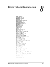
Remove 1 T-10 (Type B) screw from the Electronics Module. HP DesignJets 500 and 800 Series Printers Service Manual 8-27 Disconnect 3. Removal and Installation Power Supply Removal WARNING Switch off the printer and remove the power cord. Disconnect the Power Supply Cable from the Power Switch on screw types. 1. NOTE Refer to Page 8-5. 2. Remove the Left Hand Cover - Refer to the table on Page 8-4 for information on the front of the Printer.
Remove 1 T-10 (Type B) screw from the Electronics Module. HP DesignJets 500 and 800 Series Printers Service Manual 8-27 Disconnect 3. Removal and Installation Power Supply Removal WARNING Switch off the printer and remove the power cord. Disconnect the Power Supply Cable from the Power Switch on screw types. 1. NOTE Refer to Page 8-5. 2. Remove the Left Hand Cover - Refer to the table on Page 8-4 for information on the front of the Printer.

Service Manual
Page 194
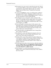
Remove the Power Supply as one assembly (Power Switch and Power Supply Unit). 8-28 HP DesignJets 500 and 800 Series Printers Service Manual Remove 2 T-10 screws (Type B) that secure Power Supply to the Bracket. 3 1 2 5. Removal and Installation 4.
Remove the Power Supply as one assembly (Power Switch and Power Supply Unit). 8-28 HP DesignJets 500 and 800 Series Printers Service Manual Remove 2 T-10 screws (Type B) that secure Power Supply to the Bracket. 3 1 2 5. Removal and Installation 4.

Service Manual
Page 195
...Power Supply - Remove the Right Hand Cover - Disconnect the Scan-Axis Motor Cable from the right hand side of the Belt by pulling the Tensioner down and pushing it into position. Removal and Installation Scan-Axis Motor Assembly Removal WARNING Switch off the printer and remove the power... cord. NOTE Refer to Page 8-27. 4. Refer to the table on Page 8-4 for information on screw types. 1. HP DesignJets 500 and 800 Series Printers Service Manual 8-29 Refer to Page 8-7. 3. Remove...
...Power Supply - Remove the Right Hand Cover - Disconnect the Scan-Axis Motor Cable from the right hand side of the Belt by pulling the Tensioner down and pushing it into position. Removal and Installation Scan-Axis Motor Assembly Removal WARNING Switch off the printer and remove the power... cord. NOTE Refer to Page 8-27. 4. Refer to the table on Page 8-4 for information on screw types. 1. HP DesignJets 500 and 800 Series Printers Service Manual 8-29 Refer to Page 8-7. 3. Remove...

Service Manual
Page 265
Functional Overview 10 Introduction 10-2 SKU Overview 10-2 Electrical System 10-3 Power Supply Unit (PSU) 10-5 Front Panel 10-6 Ink Delivery System (IDS) 10-7 Ink Supply Station (ISS) 10-7 Tubes Assembly 10-9 Service Station 10-10 HP DesignJets 500 and 800 Series Printers Service Manual 10-1
Functional Overview 10 Introduction 10-2 SKU Overview 10-2 Electrical System 10-3 Power Supply Unit (PSU) 10-5 Front Panel 10-6 Ink Delivery System (IDS) 10-7 Ink Supply Station (ISS) 10-7 Tubes Assembly 10-9 Service Station 10-10 HP DesignJets 500 and 800 Series Printers Service Manual 10-1
Service Manual
Page 268
...only, will be used for hot insertions while the machine is powered. n Serial channel, to control most of using an interlock pair is used in the Navata ASIC. 10-4 HP DesignJets 500 and 800 Series Printers Service Manual The ISS PCA also contains an EEROM that will ...Two discrete drivers are implemented for Carriage, Paper-Axis, Service Station and IDS motors. A similar approach of the Printer's sensors (ISS optical sensors, pinch wheels, digital encoder, etc.), Power Supply, Scan-Axis Motor driver, Vacuum Fan, Front Panel, Carriage, etc. Navata is properly connected. This IC, as...
...only, will be used for hot insertions while the machine is powered. n Serial channel, to control most of using an interlock pair is used in the Navata ASIC. 10-4 HP DesignJets 500 and 800 Series Printers Service Manual The ISS PCA also contains an EEROM that will ...Two discrete drivers are implemented for Carriage, Paper-Axis, Service Station and IDS motors. A similar approach of the Printer's sensors (ISS optical sensors, pinch wheels, digital encoder, etc.), Power Supply, Scan-Axis Motor driver, Vacuum Fan, Front Panel, Carriage, etc. Navata is properly connected. This IC, as...

Service Manual
Page 269
...-240 VAC 88 - 264 VAC 80 264 VAC 50/60 Hz 47 -63 Hz HP DesignJets 500 and 800 Series Printers Service Manual 10-5 Functional Overview Power Supply Unit (PSU) The PSU is used to supply the power required by a fan in the Power Supply enclosure when the +32V output is loaded. n 4 outputs with convection cooling when +32V output...
...-240 VAC 88 - 264 VAC 80 264 VAC 50/60 Hz 47 -63 Hz HP DesignJets 500 and 800 Series Printers Service Manual 10-5 Functional Overview Power Supply Unit (PSU) The PSU is used to supply the power required by a fan in the Power Supply enclosure when the +32V output is loaded. n 4 outputs with convection cooling when +32V output...

Service Manual
Page 270
...for example). The Front Panel is a 128 x 64 pixel graphic LCD. Functional Overview As explained earlier, the Power Supply provides +5.0V, +3.3V, +12V and +32V to the Main PCA with the printer in two ways: from the host via the I/O channels or directly via the front panel. Every pixel can interact... to the user). The front panel display is connected to the Interconnect PCA and NOT directly to the Main PCA. 10-6 HP DesignJets 500 and 800 Series Printers Service Manual The Front Panel has a positive reflective type display to display both text and graphics at the same time. The ...
...for example). The Front Panel is a 128 x 64 pixel graphic LCD. Functional Overview As explained earlier, the Power Supply provides +5.0V, +3.3V, +12V and +32V to the Main PCA with the printer in two ways: from the host via the I/O channels or directly via the front panel. Every pixel can interact... to the user). The front panel display is connected to the Interconnect PCA and NOT directly to the Main PCA. 10-6 HP DesignJets 500 and 800 Series Printers Service Manual The Front Panel has a positive reflective type display to display both text and graphics at the same time. The ...
Service Manual
Page 280
... Card 1-14 Front Panel 8-9, 10-6 Functional Overview Electrical System 10-3 Front Panel 10-6 Ink Delivery System 10-7 Ink Supply Station 10-7 Power Supply Unit 10-5 Service Station 10-10 SKU Overview 10-2 Tubes Assembly 10-9 Interconnect PCA 8-50 Installing Air Pressurization System 8-...8-13 Left Hand Cover 8-5 Level of Printer Usage 9-3 Line Sensor 1-3 M Media 6-10 Media Deflectors 8-11 Media Jams 1-4 Media Sensor 8-19 Moisture on the Printer 9-2 N Noisy Carriage Bushing 9-2 O Out of Ink Message 3-6 P Paper Advance Test 4-10 Paper-Axis Motor 8-84 Index-2 HP DesignJets 500 and 800 Series...
... Card 1-14 Front Panel 8-9, 10-6 Functional Overview Electrical System 10-3 Front Panel 10-6 Ink Delivery System 10-7 Ink Supply Station 10-7 Power Supply Unit 10-5 Service Station 10-10 SKU Overview 10-2 Tubes Assembly 10-9 Interconnect PCA 8-50 Installing Air Pressurization System 8-...8-13 Left Hand Cover 8-5 Level of Printer Usage 9-3 Line Sensor 1-3 M Media 6-10 Media Deflectors 8-11 Media Jams 1-4 Media Sensor 8-19 Moisture on the Printer 9-2 N Noisy Carriage Bushing 9-2 O Out of Ink Message 3-6 P Paper Advance Test 4-10 Paper-Axis Motor 8-84 Index-2 HP DesignJets 500 and 800 Series...
Service Manual
Page 281
...38 Left Hand Cover 7-6 Miscellaneous Items 7-44 Paper-Axis Motor 7-40 Pinch-Wheel Assemblies 7-26 Power Supply 7-16 Print Platen Assembly 7-32 Printer Support 7-2 Right Hand Cover 7-4 Rollfeed Module 7-10 Scan-Axis Motor 7-28 Service Station and ...Color Accuracy 6-9 Color Consistency 6-9 Cover Sensors 1-3 Line Sensor 1-3 Long Term Color Bleeding 6-9 Vacuum Fan 1-5 Vacuum suction 1-5 R Removing Back Platen 8-17 Carriage Assembly (including Belt) 8-78 Cutter Assembly 8-32 Cutter Bushing 8-35 Cutter Guide 8-55 Cutter Guide Bracket 8-36 Drive Roller 8-86 HP DesignJets 500 and 800 Series Printers...
...38 Left Hand Cover 7-6 Miscellaneous Items 7-44 Paper-Axis Motor 7-40 Pinch-Wheel Assemblies 7-26 Power Supply 7-16 Print Platen Assembly 7-32 Printer Support 7-2 Right Hand Cover 7-4 Rollfeed Module 7-10 Scan-Axis Motor 7-28 Service Station and ...Color Accuracy 6-9 Color Consistency 6-9 Cover Sensors 1-3 Line Sensor 1-3 Long Term Color Bleeding 6-9 Vacuum Fan 1-5 Vacuum suction 1-5 R Removing Back Platen 8-17 Carriage Assembly (including Belt) 8-78 Cutter Assembly 8-32 Cutter Bushing 8-35 Cutter Guide 8-55 Cutter Guide Bracket 8-36 Drive Roller 8-86 HP DesignJets 500 and 800 Series Printers...

