Service Manual
Page 9
Hard-disk accessory (HP Color LaserJet 4600 and 4650 models 131 CPU...131 Printer memory...132 Read-only memory 132 Random-access memory 132 DIMM slots (HP Color LaserJet 4600 Series printer 132 Firmware DIMM (HP Color LaserJet 4600 models 132 Flash memory (HP Color LaserJet 4610n and 4650 models 132 Nonvolatile memory 132 PJL overview...133 PML...133 Control panel...133 Laser/scanner assembly...134 Scanner-motor control...135 Image-formation...
Hard-disk accessory (HP Color LaserJet 4600 and 4650 models 131 CPU...131 Printer memory...132 Read-only memory 132 Random-access memory 132 DIMM slots (HP Color LaserJet 4600 Series printer 132 Firmware DIMM (HP Color LaserJet 4600 models 132 Flash memory (HP Color LaserJet 4610n and 4650 models 132 Nonvolatile memory 132 PJL overview...133 PML...133 Control panel...133 Laser/scanner assembly...134 Scanner-motor control...135 Image-formation...

Service Manual
Page 11
......214 Low-voltage power supply 215 Power-supply fan (HP Color LaserJet 4610n and 4650 models 217 Formatter case 218 Laser/scanner components 220 Remove the laser/scanner cover plate 220 Remove the laser/scanner retaining bars 222 To remove the laser/scanner assemblies 224 Internal components (right side 225 High-voltage power ...Fuser delivery sensor 235 Output-bin-full sensor 236 Cartridge fan...237 Formatter fan...238 Optional 500-sheet paper feeder (HP Color LaserJet 4600 and 4650 models only 239 500-sheet paper feeder top cover plate 239 500-sheet paper feeder drive unit 240 500...
......214 Low-voltage power supply 215 Power-supply fan (HP Color LaserJet 4610n and 4650 models 217 Formatter case 218 Laser/scanner components 220 Remove the laser/scanner cover plate 220 Remove the laser/scanner retaining bars 222 To remove the laser/scanner assemblies 224 Internal components (right side 225 High-voltage power ...Fuser delivery sensor 235 Output-bin-full sensor 236 Cartridge fan...237 Formatter fan...238 Optional 500-sheet paper feeder (HP Color LaserJet 4600 and 4650 models only 239 500-sheet paper feeder top cover plate 239 500-sheet paper feeder drive unit 240 500...
Service Manual
Page 133
5 Theory of operation This chapter provides information about the following topics: ● Basic operation ● Engine-control system ● Laser/scanner assembly ● Image-formation system ● Pickup/feed system ● 500-sheet paper feeder ● 2 x 500-sheet feeder ENWW 117
5 Theory of operation This chapter provides information about the following topics: ● Basic operation ● Engine-control system ● Laser/scanner assembly ● Image-formation system ● Pickup/feed system ● 500-sheet paper feeder ● 2 x 500-sheet feeder ENWW 117
Service Manual
Page 150
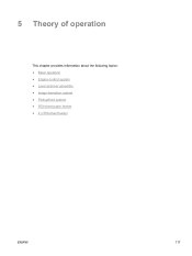
The printer has a separate laser/scanner unit for each color. Each of operation ENWW Figure 5-11 Laser/scanner system 134 Chapter 5 Theory of these has the same structure, which is shown in the print cartridge. Laser/scanner assembly The laser/scanner system receives a signal from the formatter and forms a latent image on the photosensitive drum in Figure 5-11 Laser/scanner system.
The printer has a separate laser/scanner unit for each color. Each of operation ENWW Figure 5-11 Laser/scanner system 134 Chapter 5 Theory of these has the same structure, which is shown in the print cartridge. Laser/scanner assembly The laser/scanner system receives a signal from the formatter and forms a latent image on the photosensitive drum in Figure 5-11 Laser/scanner system.

Service Manual
Page 151
Scanner-motor control The scanner-motor control rotates the scanner motor in order to place the laser beam at the correct position on the control-panel display. Figure 5-12 Scanner-motor control circuit ENWW Laser/scanner assembly 135 NOTE If a scanner-motor error occurs, the print engine stops and an error message appears on the photosensitive drum. Figure 5-12 Scanner-motor control circuit shows the circuit diagram for the scanner-motor control.
Scanner-motor control The scanner-motor control rotates the scanner motor in order to place the laser beam at the correct position on the control-panel display. Figure 5-12 Scanner-motor control circuit ENWW Laser/scanner assembly 135 NOTE If a scanner-motor error occurs, the print engine stops and an error message appears on the photosensitive drum. Figure 5-12 Scanner-motor control circuit shows the circuit diagram for the scanner-motor control.

Service Manual
Page 190
... cover removed from the laser/scanner assembly. The sheet-metal parts can have a reference number in the illustration and is not listed in the parts list, it is generally the reverse of removal. Caution regarding electrostatic discharge (ESD) The printer contains parts that are included... (optional) 174 Chapter 6 Removal and replacement ENWW Introduction This chapter explains how to remove and replace major printer components. (HP does not support repairing individual subassemblies or troubleshooting to the component level.) This chapter includes exploded-view illustrations of the...
... cover removed from the laser/scanner assembly. The sheet-metal parts can have a reference number in the illustration and is not listed in the parts list, it is generally the reverse of removal. Caution regarding electrostatic discharge (ESD) The printer contains parts that are included... (optional) 174 Chapter 6 Removal and replacement ENWW Introduction This chapter explains how to remove and replace major printer components. (HP does not support repairing individual subassemblies or troubleshooting to the component level.) This chapter includes exploded-view illustrations of the...

Service Manual
Page 236
... (callout 2). See DC controller shield. ● Right cover. See Top cover. ● Rear top cover. See Formatter case. 5 At the rear of the printer, place the cardboard spacer (included with the laser/scanner assembly) underneath the V mark on the bottom of the chassis (callout 3). 220 Chapter 6 Removal and replacement ENWW Figure 6-51 Disconnect the...
... (callout 2). See DC controller shield. ● Right cover. See Top cover. ● Rear top cover. See Formatter case. 5 At the rear of the printer, place the cardboard spacer (included with the laser/scanner assembly) underneath the V mark on the bottom of the chassis (callout 3). 220 Chapter 6 Removal and replacement ENWW Figure 6-51 Disconnect the...

Service Manual
Page 240
... distorted, and the laser beam could become skewed, resulting in the field. Failure to do so could cause the laser/scanners to the strap (callout 1). Do not disassemble it out of the printer. Then pull the laser/scanner units out of the printer. 3 For the yellow, magenta, and black laser/scanner units, first unhook each assembly from the white strap...
... distorted, and the laser beam could become skewed, resulting in the field. Failure to do so could cause the laser/scanners to the strap (callout 1). Do not disassemble it out of the printer. Then pull the laser/scanner units out of the printer. 3 For the yellow, magenta, and black laser/scanner units, first unhook each assembly from the white strap...

Service Manual
Page 320
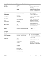
... DC controller. J1012). 4 Replace the defective laser/scanner assembly. See 304 Chapter 7 Troubleshooting ENWW See Calibrate Now (HP Color LaserJet 4600 models). 51.XY PRINTER ERROR For help press A fuser error has occurred. 1 Turn the printer off and allow it is damaged. 3 Turn the printer off and remove the fuser. Table 7-4 Numerical printer messages (HP Color LaserJet 4600 models) (continued) Message Description Action making sure...
... DC controller. J1012). 4 Replace the defective laser/scanner assembly. See 304 Chapter 7 Troubleshooting ENWW See Calibrate Now (HP Color LaserJet 4600 models). 51.XY PRINTER ERROR For help press A fuser error has occurred. 1 Turn the printer off and allow it is damaged. 3 Turn the printer off and remove the fuser. Table 7-4 Numerical printer messages (HP Color LaserJet 4600 models) (continued) Message Description Action making sure...
Service Manual
Page 321
... turn off then on board RAM. 1 Press to continue. See Calibrate Now (HP Color LaserJet 4600 models). 3 yellow An error has occurred in some printer memory. See Calibrate Now (HP Color LaserJet 4600 models). 5 Replace the DC controller PCA. J1012). 4 Replace the defective laser/scanner assembly. Table 7-4 Numerical printer messages (HP Color LaserJet 4600 models) (continued) Message Description Action To continue turn off then on 53.XY...
... turn off then on board RAM. 1 Press to continue. See Calibrate Now (HP Color LaserJet 4600 models). 3 yellow An error has occurred in some printer memory. See Calibrate Now (HP Color LaserJet 4600 models). 5 Replace the DC controller PCA. J1012). 4 Replace the defective laser/scanner assembly. Table 7-4 Numerical printer messages (HP Color LaserJet 4600 models) (continued) Message Description Action To continue turn off then on 53.XY...

Service Manual
Page 336
... and then on . 3 Reseat the connectors between the laser/ scanner and DC controller PCA (J1009 J1012). 4 Replace the defective laser/scanner assembly. See Full Calibrate Now (HP Color LaserJet 4610n and 4650 models). 5 Replace the DC controller PCA. Calibrate the printer after replacing the DC controller. Table 7-5 Numerical printer messages (HP Color LaserJet 4610n and 4650 models) (continued) Message Description Action 51.XY...
... and then on . 3 Reseat the connectors between the laser/ scanner and DC controller PCA (J1009 J1012). 4 Replace the defective laser/scanner assembly. See Full Calibrate Now (HP Color LaserJet 4610n and 4650 models). 5 Replace the DC controller PCA. Calibrate the printer after replacing the DC controller. Table 7-5 Numerical printer messages (HP Color LaserJet 4610n and 4650 models) (continued) Message Description Action 51.XY...

Service Manual
Page 430
...; The tray 2 solenoid is the lower solenoid. used during cleaning cycle ■ Color: Top position; This test activates and releases the tray 1 and tray 2 solenoids. ■ Black, Magenta, Yellow, Cyan laser/scanners. no cartridges disengaged; all cartridges disengaged; Figure 7-24 Location of the solenoids. The...Table 7-52 Solenoids Name SL1 SL2 414 Chapter 7 Troubleshooting Function Cassette pickup solenoid (paper pickup drive assembly) Multi-purpose tray pickup solenoid (paper pickup drive assembly) ENWW used during black-only printing ■ Tray1/tray 2 solenoids.
...; The tray 2 solenoid is the lower solenoid. used during cleaning cycle ■ Color: Top position; This test activates and releases the tray 1 and tray 2 solenoids. ■ Black, Magenta, Yellow, Cyan laser/scanners. no cartridges disengaged; all cartridges disengaged; Figure 7-24 Location of the solenoids. The...Table 7-52 Solenoids Name SL1 SL2 414 Chapter 7 Troubleshooting Function Cassette pickup solenoid (paper pickup drive assembly) Multi-purpose tray pickup solenoid (paper pickup drive assembly) ENWW used during black-only printing ■ Tray1/tray 2 solenoids.

Service Manual
Page 489
... Only 2 Static eliminator; 4600 Only 3 Color-registration-detection assembly 4 Paper pickup assembly; 4600 Only 4 Paper pickup assembly; 4610n/4650 Only 5 ETB assembly; 4600 Only 5 ETB assembly; 4610n/4650 Only 6 Cap, right 7 Spring, tension 8 Cap, left 9 Developing disengaging drive assembly 10 Damper assembly (top cover hinge) 11 Fuser drive assembly; 4600 Only 11 Fuser drive assembly; 4610n/4650 Only 12 Laser/scanner assembly; 4600 Only 12 Laser/scanner assembly 4610n/4650 Only...
... Only 2 Static eliminator; 4600 Only 3 Color-registration-detection assembly 4 Paper pickup assembly; 4600 Only 4 Paper pickup assembly; 4610n/4650 Only 5 ETB assembly; 4600 Only 5 ETB assembly; 4610n/4650 Only 6 Cap, right 7 Spring, tension 8 Cap, left 9 Developing disengaging drive assembly 10 Damper assembly (top cover hinge) 11 Fuser drive assembly; 4600 Only 11 Fuser drive assembly; 4610n/4650 Only 12 Laser/scanner assembly; 4600 Only 12 Laser/scanner assembly 4610n/4650 Only...

Service Manual
Page 527
...assembly (new) HVT terminal assembly Laser/scanner assembly 4610n/4650 Only Part number Table and page VD7-2356-301CN Internal components (5 of 5) VD7-1732-002CN Internal components (5 of 5) VD7-0644-001CN Internal components (5 of 5) VD7-1838-001CN Internal components (5 of 5) RG5-6517-110CN Internal components (4 of 5) RG5-6493-190CN 4600 Fuser assembly Only RG5-7450-110CN Fuser assembly... (5 of 5) RB2-8122-020CN Internal components (5 of 5) C9660-69022 Printer PCAs RG5-6395-000CN Printer PCAs C9660-69022 Internal components (3 of 5) RG5-6395-000CN Internal components ...
...assembly (new) HVT terminal assembly Laser/scanner assembly 4610n/4650 Only Part number Table and page VD7-2356-301CN Internal components (5 of 5) VD7-1732-002CN Internal components (5 of 5) VD7-0644-001CN Internal components (5 of 5) VD7-1838-001CN Internal components (5 of 5) RG5-6517-110CN Internal components (4 of 5) RG5-6493-190CN 4600 Fuser assembly Only RG5-7450-110CN Fuser assembly... (5 of 5) RB2-8122-020CN Internal components (5 of 5) C9660-69022 Printer PCAs RG5-6395-000CN Printer PCAs C9660-69022 Internal components (3 of 5) RG5-6395-000CN Internal components ...

Service Manual
Page 528
Table 8-27 Alphabetical parts list (continued) Description Laser/scanner assembly; 4600 Only LED PCA assembly Left cover Lever, cartridge pressure Low-voltage power supply, 110 V (exchange) Low-voltage power supply, 110 V (new) Low-voltage power supply, 220 V Low-voltage power-supply assembly, 110 V Low-voltage power-supply assembly, 220 V Memory controller PCA Memory tag antenna PCA Memory-tag...
Table 8-27 Alphabetical parts list (continued) Description Laser/scanner assembly; 4600 Only LED PCA assembly Left cover Lever, cartridge pressure Low-voltage power supply, 110 V (exchange) Low-voltage power supply, 110 V (new) Low-voltage power supply, 220 V Low-voltage power-supply assembly, 110 V Low-voltage power-supply assembly, 220 V Memory controller PCA Memory tag antenna PCA Memory-tag...

Service Manual
Page 533
Table 8-28 Numerical parts list (continued) Part number Description RG5-6390-000CN Laser/scanner assembly; 4600 Only RG5-6391-000CN DC controller PCA assembly; 4600 Only RG5-6391-100CN DC controller PCA (new); 4600 Only RG5-6392-000CN Paper pickup PCA RG5-6392-000CN Paper-sensor PCA assembly RG5-6393-000CN Toner sensor PCA RG5-6393-000CN Toner-sensor...
Table 8-28 Numerical parts list (continued) Part number Description RG5-6390-000CN Laser/scanner assembly; 4600 Only RG5-6391-000CN DC controller PCA assembly; 4600 Only RG5-6391-100CN DC controller PCA (new); 4600 Only RG5-6392-000CN Paper pickup PCA RG5-6392-000CN Paper-sensor PCA assembly RG5-6393-000CN Toner sensor PCA RG5-6393-000CN Toner-sensor...

Service Manual
Page 543
...statement 35 Japanese VCCI statement 34 Jetadmin, HP Web 78 Jetdirect print servers configuring 77 connecting 59 EIO slots 62 installing (4600 and 4650) 114 installing (4610n) ...printer PJL 133, 364 supported 5 laser beam exposure operations 144 laser statement for Finland 35 laser/scanner assemblies, removing 224 cover plate, removing 220 operations 134 part numbers 473, 512, 517 retaining bars, removing 222 LaserJet Tough paper 26 LaserJet... supported 64 software included 69 Manual color settings 348 manuals 42, 457 matching colors 345, 346 media colored paper 24 default size 427 driver ...
...statement 35 Japanese VCCI statement 34 Jetadmin, HP Web 78 Jetdirect print servers configuring 77 connecting 59 EIO slots 62 installing (4600 and 4650) 114 installing (4610n) ...printer PJL 133, 364 supported 5 laser beam exposure operations 144 laser statement for Finland 35 laser/scanner assemblies, removing 224 cover plate, removing 220 operations 134 part numbers 473, 512, 517 retaining bars, removing 222 LaserJet Tough paper 26 LaserJet... supported 64 software included 69 Manual color settings 348 manuals 42, 457 matching colors 345, 346 media colored paper 24 default size 427 driver ...

Service Manual
Page 545
...drivers 68 output bin delivery unit operations 166 full sensor, removing 236 locating (4600) 9 locating (4610n) 10 locating (4650) 11 output quality, troubleshooting after jams 345 blank images 353 blank spots 357 blurring 358 color 345, 350, 352, 353, 356 dark print 353 defects 351 diagnostic pages... 520 filters 465, 510, 516 fuser 491 fuser assembly 473, 511, 518 fuser drive assembly 473, 483, 511, 518 internal components 466 laser/scanner assembly 473, 512, 517 media 454 memory 455 paper pickup assembly 473, 487, 512, 518 paper pickup-drive assembly 477 PCAs 463 power supplies 471, 475, 511, ...
...drivers 68 output bin delivery unit operations 166 full sensor, removing 236 locating (4600) 9 locating (4610n) 10 locating (4650) 11 output quality, troubleshooting after jams 345 blank images 353 blank spots 357 blurring 358 color 345, 350, 352, 353, 356 dark print 353 defects 351 diagnostic pages... 520 filters 465, 510, 516 fuser 491 fuser assembly 473, 511, 518 fuser drive assembly 473, 483, 511, 518 internal components 466 laser/scanner assembly 473, 512, 517 media 454 memory 455 paper pickup assembly 473, 487, 512, 518 paper pickup-drive assembly 477 PCAs 463 power supplies 471, 475, 511, ...


