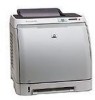
HP 2600n Parts Diagram - Color LaserJet Laser Printer
HP 2600n Parts Diagram
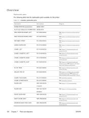
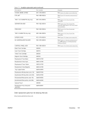
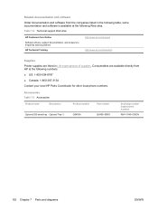
Related Manual Pages


Similar Questions

Please,tell And Show Me The Inside Parts Of Hp Laserjet P3005 Printer
I want to now the details of internal parts of HP LaserJet p3005 for maintenance purpose. So, highl...
I want to now the details of internal parts of HP LaserJet p3005 for maintenance purpose. So, highl...
(Posted by Siyoumjembereb 11 years ago)

Order For Warn-out Part
I need a telephone number for HP South Africa to place an order for a certain warn-out part from my ...
I need a telephone number for HP South Africa to place an order for a certain warn-out part from my ...
(Posted by dudu 12 years ago)

Part Number Needed For A Maintenance Kit.
I need the part number for a maintenance kit and also the part number for a fusing unit.
I need the part number for a maintenance kit and also the part number for a fusing unit.
(Posted by annejensen 13 years ago)