
Service Manual
Page 10
... Window 8-30 Top Cover 8-31 Back Cover 8-32 Scan-axis Motor Assembly 8-33 Encoder Strip 8-34 Tensioner 8-37 Trailing Cable 8-39 Cutter Assembly 8-42 Carriage Assembly and Belt 8-44 Tubes System Assembly 8-53 Ink Leak Detector Assembly 8-60 Front...Guide 8-71 Pinch-Wheel Assembly and Cam 8-73 Preventive Maintenance 9-1 Moisture on the Printer 9-2 Noisy Carriage Bushing 9-2 Belt Swelling 9-2 Cleaning the Printer 9-2 General Cleaning 9-2 Cleaning the Overdrive 9-3 Scheduled Maintenance 9-3 Level of Printer Usage 9-3 Scan-axis Maintenance 9-4 8 HP DesignJets 1050C and 1055CM Printers Service Manual
... Window 8-30 Top Cover 8-31 Back Cover 8-32 Scan-axis Motor Assembly 8-33 Encoder Strip 8-34 Tensioner 8-37 Trailing Cable 8-39 Cutter Assembly 8-42 Carriage Assembly and Belt 8-44 Tubes System Assembly 8-53 Ink Leak Detector Assembly 8-60 Front...Guide 8-71 Pinch-Wheel Assembly and Cam 8-73 Preventive Maintenance 9-1 Moisture on the Printer 9-2 Noisy Carriage Bushing 9-2 Belt Swelling 9-2 Cleaning the Printer 9-2 General Cleaning 9-2 Cleaning the Overdrive 9-3 Scheduled Maintenance 9-3 Level of Printer Usage 9-3 Scan-axis Maintenance 9-4 8 HP DesignJets 1050C and 1055CM Printers Service Manual
Service Manual
Page 43
n Replace the Trailing Cable ⇒ Page 8-39. WARNING Only replace one of the Printheads has gone above the maximum Temperature). Magenta Printhead Failed. Yellow Printhead Failed. System Error: ...this procedure you will be able to Chapter 2). Error Data: Í 00000000 Í 00000001 Í 00000002 Í 00000003 Cyan Printhead Failed. HP DesignJets 1050C and 1055CM Printers Service Manual 2-9 n Make sure that the Trailing Cable is using a 3rd Party RIP. n If the error code continues, replace the Electronics Module ⇒ Page 8-25. n Replace the Carriage Assembly...
n Replace the Trailing Cable ⇒ Page 8-39. WARNING Only replace one of the Printheads has gone above the maximum Temperature). Magenta Printhead Failed. Yellow Printhead Failed. System Error: ...this procedure you will be able to Chapter 2). Error Data: Í 00000000 Í 00000001 Í 00000002 Í 00000003 Cyan Printhead Failed. HP DesignJets 1050C and 1055CM Printers Service Manual 2-9 n Make sure that the Trailing Cable is using a 3rd Party RIP. n If the error code continues, replace the Electronics Module ⇒ Page 8-25. n Replace the Carriage Assembly...
Service Manual
Page 44
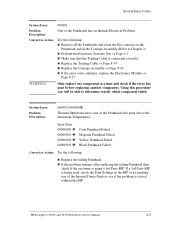
...continues, replace the Electronics Module ⇒ Page 8-25. n Replace the Trailing Cable ⇒ Page 8-39. n If the Error Code continues, replace the Electronics Module ⇒ Page 8-25. n Replace the Trailing Cable ⇒ Page 8-39. WARNING Only replace one component at a time and... Description: Error in the Carriage Assembly (Refer to determine exactly which component failed. 2-10 HP DesignJets 1050C and 1055CM Printers Service Manual System Error Codes System Error: 060309 Problem Description: Problem with setting the Voltage of the Printheads.
...continues, replace the Electronics Module ⇒ Page 8-25. n Replace the Trailing Cable ⇒ Page 8-39. n If the Error Code continues, replace the Electronics Module ⇒ Page 8-25. n Replace the Trailing Cable ⇒ Page 8-39. WARNING Only replace one component at a time and... Description: Error in the Carriage Assembly (Refer to determine exactly which component failed. 2-10 HP DesignJets 1050C and 1055CM Printers Service Manual System Error Codes System Error: 060309 Problem Description: Problem with setting the Voltage of the Printheads.
Service Manual
Page 54
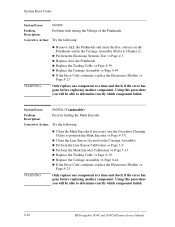
Corrective Action: Turn the Printer OFF and disconnect the trailing cable. Power ON the Printer and check if the Error Code disappears. System Error: 0B0007 Problem Description: Unable to the Electronics Module. Corrective Action: Replace the Electronics Module ⇒ Page 8-25. 2-20 HP DesignJets 1050C and 1055CM Printers Service Manual n If the New Vacuum Fan does not function correctly...
Corrective Action: Turn the Printer OFF and disconnect the trailing cable. Power ON the Printer and check if the Error Code disappears. System Error: 0B0007 Problem Description: Unable to the Electronics Module. Corrective Action: Replace the Electronics Module ⇒ Page 8-25. 2-20 HP DesignJets 1050C and 1055CM Printers Service Manual n If the New Vacuum Fan does not function correctly...

Service Manual
Page 77
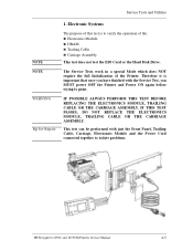
...The Service Tests work in a special Mode which does NOT require the full Initialization of all internal Service Tests available in the Printer. n Trailing Cable. HP DesignJets 1050C and 1055CM Printers Service Manual 4-3 n Carriage Assembly. 2 EIO Card ⇒ Page 4-10 The purpose of this test is to verify ...: n Service Replaceable Kit (SRK). Service Tests and Utilities Service Tests (Diagnostics) WARNING The following is a list of the Printer. Instructions for entering the Service Tests menu are given on Page 4-4. Therefore it is important that once you have finished with the...
...The Service Tests work in a special Mode which does NOT require the full Initialization of all internal Service Tests available in the Printer. n Trailing Cable. HP DesignJets 1050C and 1055CM Printers Service Manual 4-3 n Carriage Assembly. 2 EIO Card ⇒ Page 4-10 The purpose of this test is to verify ...: n Service Replaceable Kit (SRK). Service Tests and Utilities Service Tests (Diagnostics) WARNING The following is a list of the Printer. Instructions for entering the Service Tests menu are given on Page 4-4. Therefore it is important that once you have finished with the...
Service Manual
Page 79
... test can be performed with the Service Test, you have finished with just the Front Panel, Trailing Cable, Carriage, Electronics Module and the Power Cord connected together to isolate problems. HP DesignJets 1050C and 1055CM Printers Service Manual 4-5 Service Tests and Utilities NOTE NOTE WARNING Tip for Repair 1. n DRAM. The Service Tests work in a special Mode...
... test can be performed with the Service Test, you have finished with just the Front Panel, Trailing Cable, Carriage, Electronics Module and the Power Cord connected together to isolate problems. HP DesignJets 1050C and 1055CM Printers Service Manual 4-5 Service Tests and Utilities NOTE NOTE WARNING Tip for Repair 1. n DRAM. The Service Tests work in a special Mode...

Service Manual
Page 80
... XXXXXXXX DRAM access functionality ELECTRONIC SYSTEMS Running Carriage Test XXXXXXXX XXXXXXXX XXXXXXXX Trailing Cable Test Yuyu R/W Carriage ADC Pen Continuity Digital Cyan / Magenta / Yellow / Black PEN ACUMEN Pen Digital functionality Pen Analog Continuity VPP regulation Cyan / Magenta / Yellow / Black Line Sensor zero test 4-6 HP DesignJets 1050C and 1055CM Printers Service Manual Electronic Systems" and press Enter.
... XXXXXXXX DRAM access functionality ELECTRONIC SYSTEMS Running Carriage Test XXXXXXXX XXXXXXXX XXXXXXXX Trailing Cable Test Yuyu R/W Carriage ADC Pen Continuity Digital Cyan / Magenta / Yellow / Black PEN ACUMEN Pen Digital functionality Pen Analog Continuity VPP regulation Cyan / Magenta / Yellow / Black Line Sensor zero test 4-6 HP DesignJets 1050C and 1055CM Printers Service Manual Electronic Systems" and press Enter.

Service Manual
Page 81
...: 6.0A77R DIMM1: EDO 32MB 60ns DIMM2: EDO 16 MB 60ns WARNING IF THIS TEST PASSES, DO NOT REPLACE THE ELECTRONICS MODULE, TRAILING CABLE OR THE CARRIAGE ASSEMBLY. 4 If the test fails. Perform the Electronic Systems Test again. Electronics Failure If there is a problem with...front panel: ELECTRONIC SYSTEMS Possible Failure on: 1. Reseat the DRAM DIMMs (Memory Modules), reconnect the power cord and power On the Printer. HP DesignJets 1050C and 1055CM Printers Service Manual 4-7 DRAM DIMMs 2. Electronics Module Code: 00XXXX:0000XX In this case, try one of the following: 1 Switch the...
...: 6.0A77R DIMM1: EDO 32MB 60ns DIMM2: EDO 16 MB 60ns WARNING IF THIS TEST PASSES, DO NOT REPLACE THE ELECTRONICS MODULE, TRAILING CABLE OR THE CARRIAGE ASSEMBLY. 4 If the test fails. Perform the Electronic Systems Test again. Electronics Failure If there is a problem with...front panel: ELECTRONIC SYSTEMS Possible Failure on: 1. Reseat the DRAM DIMMs (Memory Modules), reconnect the power cord and power On the Printer. HP DesignJets 1050C and 1055CM Printers Service Manual 4-7 DRAM DIMMs 2. Electronics Module Code: 00XXXX:0000XX In this case, try one of the following: 1 Switch the...
Service Manual
Page 82
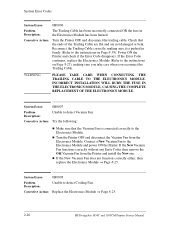
... a problem with the Trailing Cable then the following : 1 Make sure that the Trailing Cable is connected correctly. 2 Power OFF the Printer and connect a new Trailing Cable to determine exactly which component failed. Carriage 3. Electronics Module Code: 00XXXX:0000XX WARNING In this procedure you will be able to determine exactly which component failed. 4-8 HP DesignJets 1050C and 1055CM Printers Service Manual If...
... a problem with the Trailing Cable then the following : 1 Make sure that the Trailing Cable is connected correctly. 2 Power OFF the Printer and connect a new Trailing Cable to determine exactly which component failed. Carriage 3. Electronics Module Code: 00XXXX:0000XX WARNING In this procedure you will be able to determine exactly which component failed. 4-8 HP DesignJets 1050C and 1055CM Printers Service Manual If...
Service Manual
Page 83
... 2. If the test PASSES, replace the Trailing Cable ⇒ Page 8-39. 5 Power OFF the Printer and connect a new Carriage Assembly to the Trailing Cable (without removing the old Carriage Assembly from the Printer). Perform this test again and if the test FAILS, then DO NOT replace the Electronics Module. HP DesignJets 1050C and 1055CM Printers Service Manual 4-9 Perform this procedure...
... 2. If the test PASSES, replace the Trailing Cable ⇒ Page 8-39. 5 Power OFF the Printer and connect a new Carriage Assembly to the Trailing Cable (without removing the old Carriage Assembly from the Printer). Perform this test again and if the test FAILS, then DO NOT replace the Electronics Module. HP DesignJets 1050C and 1055CM Printers Service Manual 4-9 Perform this procedure...

Service Manual
Page 190
Parts and Diagrams Carriage Assembly Reference on Drawing 1 2 3 4 5 - Printer Support HP Part Number Quantity Description/Comments C6072-60147 C6072-60200 0624-0737 3050-1982 C6072-60196 C6071-60166 1 Carriage Assembly (Includes Carriage Height Tool, Cutter Assembly and Line Sensor) 1 Cutter Assembly (Includes Screw and Washer) 1 Screw 1 Washer 1 Trailing Cable (Includes Nye Oil, Trailing Cable Clip, Cover Cap, Trailing Ferrite and Ferrite Pincer) 1 Carriage Height Tool (Also Included with the Carriage Assembly) 7-18 HP DesignJets 1050C and 1055CM Printers Service Manual
Parts and Diagrams Carriage Assembly Reference on Drawing 1 2 3 4 5 - Printer Support HP Part Number Quantity Description/Comments C6072-60147 C6072-60200 0624-0737 3050-1982 C6072-60196 C6071-60166 1 Carriage Assembly (Includes Carriage Height Tool, Cutter Assembly and Line Sensor) 1 Cutter Assembly (Includes Screw and Washer) 1 Screw 1 Washer 1 Trailing Cable (Includes Nye Oil, Trailing Cable Clip, Cover Cap, Trailing Ferrite and Ferrite Pincer) 1 Carriage Height Tool (Also Included with the Carriage Assembly) 7-18 HP DesignJets 1050C and 1055CM Printers Service Manual
Service Manual
Page 209
... Trailing Cable 8-39 Cutter Assembly 8-42 Carriage Assembly and Belt 8-44 Tubes System Assembly 8-53 Ink Leak Detector Assembly 8-60 Front Platen Assembly 8-62 Platen Assembly 8-63 Paper Entry Assembly 8-64 Roller Guide 8-66 Media Holder Strip 8-69 Drive Roller 8-70 Center Guide 8-71 Pinch-Wheel Assembly and Cam 8-73 HP DesignJets 1050C and 1055CM Printers...
... Trailing Cable 8-39 Cutter Assembly 8-42 Carriage Assembly and Belt 8-44 Tubes System Assembly 8-53 Ink Leak Detector Assembly 8-60 Front Platen Assembly 8-62 Platen Assembly 8-63 Paper Entry Assembly 8-64 Roller Guide 8-66 Media Holder Strip 8-69 Drive Roller 8-70 Center Guide 8-71 Pinch-Wheel Assembly and Cam 8-73 HP DesignJets 1050C and 1055CM Printers...
Service Manual
Page 233
... to 7, refer to the Electronics Module. Remove the DIMMs by releasing it from the rear of the electronics module. Disconnect the Trailing Cable by releasing the retaining clips at the top and bottom of each one, holding the outer non-metallic edge and gently pulling towards ... Hand Rear Covers" see page 8-23. Note the position of the DIMMs. From left and right side of the Printer. 1. Removal and Installation Electronics Module Refer to the Electronics Module. Store these parts in the 1st and 2nd slot (item 3). HP DesignJets 1050C and 1055CM Printers Service Manual 8-25
... to 7, refer to the Electronics Module. Remove the DIMMs by releasing it from the rear of the electronics module. Disconnect the Trailing Cable by releasing the retaining clips at the top and bottom of each one, holding the outer non-metallic edge and gently pulling towards ... Hand Rear Covers" see page 8-23. Note the position of the DIMMs. From left and right side of the Printer. 1. Removal and Installation Electronics Module Refer to the Electronics Module. Store these parts in the 1st and 2nd slot (item 3). HP DesignJets 1050C and 1055CM Printers Service Manual 8-25

Service Manual
Page 235
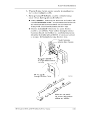
...below ) will burn an internal Electronics Module fuse. Make sure you push the Trailing Cable in which case you will not be connected to reconnect the Trailing Cable using the above steps. Before powering ON the Printer, check the continuity (using the above steps. Do NOT power ON the... Printer because you have to the 1st clip from left to right (the longest strip will NOT be visible when installed correctly Do Not install a damaged Trailing Cable HP DesignJets 1050C and 1055CM Printers Service Manual C607440 8-27 n If there is no ...
...below ) will burn an internal Electronics Module fuse. Make sure you push the Trailing Cable in which case you will not be connected to reconnect the Trailing Cable using the above steps. Before powering ON the Printer, check the continuity (using the above steps. Do NOT power ON the... Printer because you have to the 1st clip from left to right (the longest strip will NOT be visible when installed correctly Do Not install a damaged Trailing Cable HP DesignJets 1050C and 1055CM Printers Service Manual C607440 8-27 n If there is no ...
Service Manual
Page 247
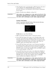
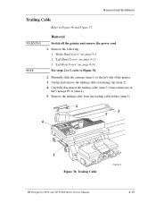
... 1) to Figure 36 and Figure 37. "Right Hand Cover" see page 8-4. 2. Carefully disconnect the trailing cable (item 3) from the trailing cable holder (item 5). 2 3 5 4 1 Figure 36: Trailing Cable C607412 HP DesignJets 1050C and 1055CM Printers Service Manual 8-39 Remove the following: 1. For steps 2 to 5, refer to Figure 36. 2. Remove the trailing cable from connectors in the Carriage PCA (item 4). 5. Unclip and remove the...
... 1) to Figure 36 and Figure 37. "Right Hand Cover" see page 8-4. 2. Carefully disconnect the trailing cable (item 3) from the trailing cable holder (item 5). 2 3 5 4 1 Figure 36: Trailing Cable C607412 HP DesignJets 1050C and 1055CM Printers Service Manual 8-39 Remove the following: 1. For steps 2 to 5, refer to Figure 36. 2. Remove the trailing cable from connectors in the Carriage PCA (item 4). 5. Unclip and remove the...
Service Manual
Page 248
... be connected to right (the longest strip will need replacing. 8. Make sure you should hear an audible click. 8-40 HP DesignJets 1050C and 1055CM Printers Service Manual Once the Trailing Cable is inserted, you push the Trailing Cable in straight and not bent. Start reconnecting the Trailing Cable from left to the 1st clip from the trailing cable holder (item 2) and remove. 7.
... be connected to right (the longest strip will need replacing. 8. Make sure you should hear an audible click. 8-40 HP DesignJets 1050C and 1055CM Printers Service Manual Once the Trailing Cable is inserted, you push the Trailing Cable in straight and not bent. Start reconnecting the Trailing Cable from left to the 1st clip from the trailing cable holder (item 2) and remove. 7.
Service Manual
Page 249
... an internal Electronics Module fuse. n If there is possible to reconnect the Trailing Cable using the above steps. Do NOT power ON the Printer because you have to power ON the Printer without any bubbles HP DesignJets 1050C and 1055CM Printers Service Manual 8-41 Disconnect the Trailing Cable and reconnect again using a tester) between the two points, then it is...
... an internal Electronics Module fuse. n If there is possible to reconnect the Trailing Cable using the above steps. Do NOT power ON the Printer because you have to power ON the Printer without any bubbles HP DesignJets 1050C and 1055CM Printers Service Manual 8-41 Disconnect the Trailing Cable and reconnect again using a tester) between the two points, then it is...
Service Manual
Page 254
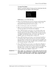
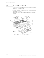
Unclip and remove the trailing cable restraining clip (item 2) from the trailing cable holder (item 5). 2 4 3 5 1 C607412 Figure 43: Carriage Assembly and Belt 8-46 HP DesignJets 1050C and 1055CM Printers Service Manual Remove the trailing cable (item 3) from the Carriage Assembly (item 1). 7. Carefully disconnect the trailing cable (item 3) from connectors in the Carriage PCA (item 4). 8. Removal and Installation NOTE For steps 6 to 8, refer to Figure 43. 6.
Unclip and remove the trailing cable restraining clip (item 2) from the trailing cable holder (item 5). 2 4 3 5 1 C607412 Figure 43: Carriage Assembly and Belt 8-46 HP DesignJets 1050C and 1055CM Printers Service Manual Remove the trailing cable (item 3) from the Carriage Assembly (item 1). 7. Carefully disconnect the trailing cable (item 3) from connectors in the Carriage PCA (item 4). 8. Removal and Installation NOTE For steps 6 to 8, refer to Figure 43. 6.
Service Manual
Page 259
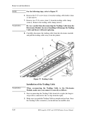
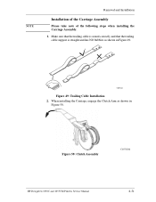
C607441 Figure 49: Trailing Cable Installation 2. Make sure that the trailing cable is seated correctly and that the trailing cable support is straight and has NO bubbles as shown in Figure 49. Figure 50: Clutch Assembly C607420d HP DesignJets 1050C and 1055CM Printers Service Manual 8-51 When installing the Carriage, engage the Clutch Arm as shown in Figure 50. NOTE Removal and Installation Installation of the Carriage Assembly Please take note of the following steps when installing the Carriage Assembly. 1.
C607441 Figure 49: Trailing Cable Installation 2. Make sure that the trailing cable is seated correctly and that the trailing cable support is straight and has NO bubbles as shown in Figure 49. Figure 50: Clutch Assembly C607420d HP DesignJets 1050C and 1055CM Printers Service Manual 8-51 When installing the Carriage, engage the Clutch Arm as shown in Figure 50. NOTE Removal and Installation Installation of the Carriage Assembly Please take note of the following steps when installing the Carriage Assembly. 1.
Service Manual
Page 316
...Hand Cover 8-6 Trailing Cable 8-40 Interface Specifications 10-17 ISS Assembly 7-14 L Leak Detect System 10-8 Left Hand Cover 7-10, 8-13 Left Hand Trim 8-18 Left Rear Cover 8-24 Level of Printer Usage 9-3 ...Line Sensor Calibration 5-9 Long term bleed 1-12 Lower image gloss 1-13 M Media 6-24 Media Holder Strip 8-69 Media Jams 1-7 Media Sensor 7-30, 8-29 Memory Specifications 10-13 Moisture on the Printer 9-2 N No Printing Defects 6-21 Noisy Carriage Bushing 9-2 Nozzle Defects 6-7 Nozzle Print Test 6-6 O Overdrive Cleaning 4-37 Index-2 HP DesignJets 1050C and 1055CM Printers...
...Hand Cover 8-6 Trailing Cable 8-40 Interface Specifications 10-17 ISS Assembly 7-14 L Leak Detect System 10-8 Left Hand Cover 7-10, 8-13 Left Hand Trim 8-18 Left Rear Cover 8-24 Level of Printer Usage 9-3 ...Line Sensor Calibration 5-9 Long term bleed 1-12 Lower image gloss 1-13 M Media 6-24 Media Holder Strip 8-69 Media Jams 1-7 Media Sensor 7-30, 8-29 Memory Specifications 10-13 Moisture on the Printer 9-2 N No Printing Defects 6-21 Noisy Carriage Bushing 9-2 Nozzle Defects 6-7 Nozzle Print Test 6-6 O Overdrive Cleaning 4-37 Index-2 HP DesignJets 1050C and 1055CM Printers...


