Owners Manual
Page 7
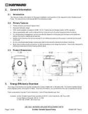
... built-in Watts. The EcoStar Variable Speed Pump displays power consumption in protection for high temperatures and voltage fluctuations. Cost of electricity = $0.10 per kWh Convert Watts to withstand temperatures below freezing without the need for the proper installation and operation of 36 USE ONLY HAYWARD GENUINE REPLACEMENT PARTS EcoStar Variable Speed Pump IS3401VSP Rev-2 Primary Features ...
... built-in Watts. The EcoStar Variable Speed Pump displays power consumption in protection for high temperatures and voltage fluctuations. Cost of electricity = $0.10 per kWh Convert Watts to withstand temperatures below freezing without the need for the proper installation and operation of 36 USE ONLY HAYWARD GENUINE REPLACEMENT PARTS EcoStar Variable Speed Pump IS3401VSP Rev-2 Primary Features ...
Owners Manual
Page 15
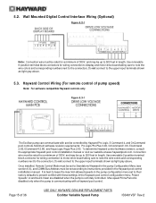
...display and motor drive board taking care to note the wire colors and corresponding numbers next to instructions provided in the Hayward pool control configuration menu. Use removable 6-position terminal block connectors for a minimum of pump speed) Note: For software compatible Hayward controls only Figure 5.3-1 The EcoStar pump... controlled. Use removable 2-position terminal block connector for a minimum of 36 USE ONLY HAYWARD GENUINE REPLACEMENT PARTS EcoStar Variable Speed Pump IS3401VSP Rev-2 Do not connect to the upper input terminals shown as light gray above...
...display and motor drive board taking care to note the wire colors and corresponding numbers next to instructions provided in the Hayward pool control configuration menu. Use removable 6-position terminal block connectors for a minimum of pump speed) Note: For software compatible Hayward controls only Figure 5.3-1 The EcoStar pump... controlled. Use removable 2-position terminal block connector for a minimum of 36 USE ONLY HAYWARD GENUINE REPLACEMENT PARTS EcoStar Variable Speed Pump IS3401VSP Rev-2 Do not connect to the upper input terminals shown as light gray above...
Owners Manual
Page 16
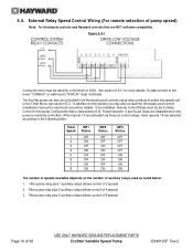
...pool control installation manual for electrical connection details. Filter pump relay plus 3 auxiliary relays allows control of 8 speeds Page 16 of 2 speeds 2. Filter pump relay plus 1 auxiliary relays allows control of 36 USE ONLY HAYWARD GENUINE REPLACEMENT PARTS EcoStar Variable Speed Pump IS3401VSP Rev-2 See section 6.6.11 for a minimum...INP3 Status OFF OFF OFF OFF ON ON ON ON The number of speeds available depends on the number of 300V. In addition to the lower "COMBUS" or wall mount "DISPLAY" data terminals. Once installed, Remote Control Mode must be rated for more...
...pool control installation manual for electrical connection details. Filter pump relay plus 3 auxiliary relays allows control of 8 speeds Page 16 of 2 speeds 2. Filter pump relay plus 1 auxiliary relays allows control of 36 USE ONLY HAYWARD GENUINE REPLACEMENT PARTS EcoStar Variable Speed Pump IS3401VSP Rev-2 See section 6.6.11 for a minimum...INP3 Status OFF OFF OFF OFF ON ON ON ON The number of speeds available depends on the number of 300V. In addition to the lower "COMBUS" or wall mount "DISPLAY" data terminals. Once installed, Remote Control Mode must be rated for more...
Owners Manual
Page 19
... mode to indicate that all bathers are out of 36 USE ONLY HAYWARD GENUINE REPLACEMENT PARTS EcoStar Variable Speed Pump IS3401VSP Rev-2 MIN Allowed Speed e. Low Temp Speed k. Start/Stop Time for Timer "X" (where "X" equals 1 through 4) c. Speed "X" Name (where "X" equals 1 through 8) d. Drive Serial Number...will be prompted to change parameters. 3. Drive Temp Setting 2. Motor Drive/Display Firmware Revisions c. The < and > arrow buttons are used to stop the pump to program the 4 preset speeds) a. For SP3400VSPVR, it will also flash on and off when the ...
... mode to indicate that all bathers are out of 36 USE ONLY HAYWARD GENUINE REPLACEMENT PARTS EcoStar Variable Speed Pump IS3401VSP Rev-2 MIN Allowed Speed e. Low Temp Speed k. Start/Stop Time for Timer "X" (where "X" equals 1 through 4) c. Speed "X" Name (where "X" equals 1 through 8) d. Drive Serial Number...will be prompted to change parameters. 3. Drive Temp Setting 2. Motor Drive/Display Firmware Revisions c. The < and > arrow buttons are used to stop the pump to program the 4 preset speeds) a. For SP3400VSPVR, it will also flash on and off when the ...
Owners Manual
Page 20
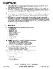
Initial startup After plumbing and wiring are displayed. Configuration Menu press > to enter Use > to next item 4. to adjust, > go to enter Configuration Menu 3. Time: Th 1:27PM +- Use + to next menu item +- Speed Selection rpm 7. Set maximum running speed of 36 USE ONLY HAYWARD GENUINE REPLACEMENT PARTS EcoStar Variable Speed Pump IS3401VSP Rev-2 Screen Comments 1. Thursday 1:27p 1725rpm...
Initial startup After plumbing and wiring are displayed. Configuration Menu press > to enter Use > to next item 4. to adjust, > go to enter Configuration Menu 3. Time: Th 1:27PM +- Use + to next menu item +- Speed Selection rpm 7. Set maximum running speed of 36 USE ONLY HAYWARD GENUINE REPLACEMENT PARTS EcoStar Variable Speed Pump IS3401VSP Rev-2 Screen Comments 1. Thursday 1:27p 1725rpm...

Owners Manual
Page 22
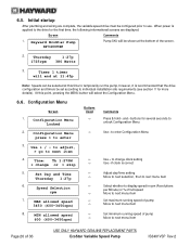
...:00 am to 12:00 pm, and Timer 2 is to start /stop times are to change displayed timer Use > to skip to enter Timer Menu 2. Options are set start at 11:45 pm. times > Use > ...to be set motor speed for yes; > to next menu item 18. 16. +- Use to set to set speed for Timer 1 is set up such that their run times overlap, the timers will... 1 1725rpm 8:00a to choose days of the week. Use to chose days of 36 USE ONLY HAYWARD GENUINE REPLACEMENT PARTS EcoStar Variable Speed Pump IS3401VSP Rev-2
...:00 am to 12:00 pm, and Timer 2 is to start /stop times are to change displayed timer Use > to skip to enter Timer Menu 2. Options are set start at 11:45 pm. times > Use > ...to be set motor speed for yes; > to next menu item 18. 16. +- Use to set to set speed for Timer 1 is set up such that their run times overlap, the timers will... 1 1725rpm 8:00a to choose days of the week. Use to chose days of 36 USE ONLY HAYWARD GENUINE REPLACEMENT PARTS EcoStar Variable Speed Pump IS3401VSP Rev-2
Owners Manual
Page 23
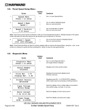
... of line voltage status connected to save the new speed setting. 6.9. For SP3400VSPVR, displays SVRS revision and current status of 36 USE ONLY HAYWARD GENUINE REPLACEMENT PARTS EcoStar Variable Speed Pump IS3401VSP Rev-2 Diagnostic Menu Screen 1. Use to rename displayed speed Move to enter Diagnostic Menu and toggle between displays 2. Diagnostic Menu Press > to enter Buttons Used Comments Use...
... of line voltage status connected to save the new speed setting. 6.9. For SP3400VSPVR, displays SVRS revision and current status of 36 USE ONLY HAYWARD GENUINE REPLACEMENT PARTS EcoStar Variable Speed Pump IS3401VSP Rev-2 Diagnostic Menu Screen 1. Use to rename displayed speed Move to enter Diagnostic Menu and toggle between displays 2. Diagnostic Menu Press > to enter Buttons Used Comments Use...
Owners Manual
Page 24
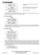
... 1. press STOP/RESUME 2. When Quick Clean is pressed, the above message will resume normal operation. 6.11. Driver: 38C Heatsink: 32C Display showing temperature of 36 USE ONLY HAYWARD GENUINE REPLACEMENT PARTS EcoStar Variable Speed Pump IS3401VSP Rev-2 Bathers in the water, pressing + will record the last twenty error and/or trip conditions, as well as...
... 1. press STOP/RESUME 2. When Quick Clean is pressed, the above message will resume normal operation. 6.11. Driver: 38C Heatsink: 32C Display showing temperature of 36 USE ONLY HAYWARD GENUINE REPLACEMENT PARTS EcoStar Variable Speed Pump IS3401VSP Rev-2 Bathers in the water, pressing + will record the last twenty error and/or trip conditions, as well as...

Owners Manual
Page 25
...be displayed while Quick Clean is activated. Remote Stop Screen 1. Remote Stop is engaged Note: The above message will also flash on and off motor. Occasionally, shaft seals must be cancelled early by pressing the Stop/Resume button, at which time the pump ...can cause components to explode, with risk of 36 USE ONLY HAYWARD GENUINE REPLACEMENT PARTS EcoStar Variable Speed Pump IS3401VSP Rev-2 ATTENTION - toxic and will not flash. 6.12. Gravity drain system as far as necessary. Hayward pumps have self-lubricating motor bearings and shaft seals. Do NOT ...
...be displayed while Quick Clean is activated. Remote Stop Screen 1. Remote Stop is engaged Note: The above message will also flash on and off motor. Occasionally, shaft seals must be cancelled early by pressing the Stop/Resume button, at which time the pump ...can cause components to explode, with risk of 36 USE ONLY HAYWARD GENUINE REPLACEMENT PARTS EcoStar Variable Speed Pump IS3401VSP Rev-2 ATTENTION - toxic and will not flash. 6.12. Gravity drain system as far as necessary. Hayward pumps have self-lubricating motor bearings and shaft seals. Do NOT ...
Owners Manual
Page 30
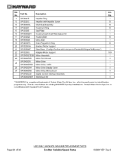
...- Page 30 of Pentair® WhisperFlo® pump*) 1 22 SPX3200Q Adapter-Motor Support 100 23 SPX3400Z1ECM Motor Assembly 1 24 SPX3400FAN Motor Fan Shroud 5 SPX3400DR Motor Drive 1 25 SPX3400DRVR Motor Drive, SVRS 1 26 SPX3400DR4 Motor Drive Display Cover 5 27 SPX3400DR2 Motor Drive Wiring Cover 5 ... 10 20 SPX3200GA Bracket, Motor Support 1 21 SPX3200WF Riser Base (To align EcoStar with Hayward Pool Products. Pentair Water Pool & Spa, Inc. is not affiliated with inlet port of 36 USE ONLY HAYWARD GENUINE REPLACEMENT PARTS EcoStar Variable Speed Pump IS3401VSP Rev-2
...- Page 30 of Pentair® WhisperFlo® pump*) 1 22 SPX3200Q Adapter-Motor Support 100 23 SPX3400Z1ECM Motor Assembly 1 24 SPX3400FAN Motor Fan Shroud 5 SPX3400DR Motor Drive 1 25 SPX3400DRVR Motor Drive, SVRS 1 26 SPX3400DR4 Motor Drive Display Cover 5 27 SPX3400DR2 Motor Drive Wiring Cover 5 ... 10 20 SPX3200GA Bracket, Motor Support 1 21 SPX3200WF Riser Base (To align EcoStar with Hayward Pool Products. Pentair Water Pool & Spa, Inc. is not affiliated with inlet port of 36 USE ONLY HAYWARD GENUINE REPLACEMENT PARTS EcoStar Variable Speed Pump IS3401VSP Rev-2
Owners Manual
Page 33
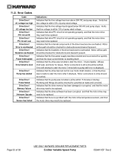
...start the motor 3 times before pump stall error is resetting itself. Check impeller, diffuser, shaft seal, and motor for obstructions and cleared if present. Drive will attempt to be replaced. Indicates that the input current limiter is displayed. Plumbing and fittings should be checked... and that the line voltage has risen above 264 VAC and pump stops. Verify that line voltage is not operating properly, and that the heatsink of 36 USE ONLY HAYWARD GENUINE REPLACEMENT PARTS EcoStar Variable Speed Pump IS3401VSP Rev-2 Indicates that the drive has lost control over motor...
...start the motor 3 times before pump stall error is resetting itself. Check impeller, diffuser, shaft seal, and motor for obstructions and cleared if present. Drive will attempt to be replaced. Indicates that the input current limiter is displayed. Plumbing and fittings should be checked... and that the line voltage has risen above 264 VAC and pump stops. Verify that line voltage is not operating properly, and that the heatsink of 36 USE ONLY HAYWARD GENUINE REPLACEMENT PARTS EcoStar Variable Speed Pump IS3401VSP Rev-2 Indicates that the drive has lost control over motor...

Technical Guide
Page 12
...sub- panel and not from the controller (fig 22). Remove the two data plugs (COMBUS & DISPLAY) from the wiring compartment (fig 23) and the 4 connector data plug from the filter pump relay. Wire colors can be run through the second (data) conduit opening and channel (Page ...as shown (fig 22 & 23). Wire 7 on the pump to 2 on the controller, 8 on the pump to 3 on the controller and 1 on 7 EcoStar is data connected to a Hayward/Goldline control, voltage needs to 1 on the pump to 4 to point. Installation-Hayward/Goldline Controls (Compatible software shown below) 1.
...sub- panel and not from the controller (fig 22). Remove the two data plugs (COMBUS & DISPLAY) from the wiring compartment (fig 23) and the 4 connector data plug from the filter pump relay. Wire colors can be run through the second (data) conduit opening and channel (Page ...as shown (fig 22 & 23). Wire 7 on the pump to 2 on the controller, 8 on the pump to 3 on the controller and 1 on 7 EcoStar is data connected to a Hayward/Goldline control, voltage needs to 1 on the pump to 4 to point. Installation-Hayward/Goldline Controls (Compatible software shown below) 1.

Technical Guide
Page 17
... 15 Programming - Default settings: Speed 1 1000 RPM 29% Speed 2 1750 RPM 51% Speed 3 2500 RPM 72% Speed 4 3250 RPM 94% Display Screen Fig 30 MENU/NAVIGATION BUTTONS The button will illuminate solid when there is an error condition. LED will illuminate once the timers have been programmed., even if the pump is selected. The & buttons are...
... 15 Programming - Default settings: Speed 1 1000 RPM 29% Speed 2 1750 RPM 51% Speed 3 2500 RPM 72% Speed 4 3250 RPM 94% Display Screen Fig 30 MENU/NAVIGATION BUTTONS The button will illuminate solid when there is an error condition. LED will illuminate once the timers have been programmed., even if the pump is selected. The & buttons are...
Technical Guide
Page 18
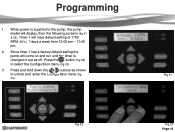
Programming 1. Press the button (fig 32) to the pump, the pump model will have default setting of 1750 RPM (50%), 7 days a week from 12:00 am - 11:45 pm. 2. Press and hold down the & buttons as off. When power is changed or set as shown to unlock and enter the Configuration menu (fig 33). Timer 1 will display, then the following screens (fig 31 & 32). Since timer 1 has a factory default setting the pump will come on and run until the timer is supplied to select the Configuration menu (fig 33). 3. Fig 31 Fig 32 Fig 33 Page 16
Programming 1. Press the button (fig 32) to the pump, the pump model will have default setting of 1750 RPM (50%), 7 days a week from 12:00 am - 11:45 pm. 2. Press and hold down the & buttons as off. When power is changed or set as shown to unlock and enter the Configuration menu (fig 33). Timer 1 will display, then the following screens (fig 31 & 32). Since timer 1 has a factory default setting the pump will come on and run until the timer is supplied to select the Configuration menu (fig 33). 3. Fig 31 Fig 32 Fig 33 Page 16
Technical Guide
Page 32
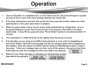
Auto Prime and the 3 minute prime only works in watts will begin to be displayed on the display while the pump is a trip, both the Stop/Resume and Check System lights will be illuminated and the trip message below will go into the prime mode selected ... or timed. If the error message does not clear, cycle off the power to restart the pump. When the pump starts it will be replaced. 6. Once configuration is completed and 1 or more of the speed buttons or the quick clean button is not achieved within 15 minutes. 4. The consumption in the stand alone...
Auto Prime and the 3 minute prime only works in watts will begin to be displayed on the display while the pump is a trip, both the Stop/Resume and Check System lights will be illuminated and the trip message below will go into the prime mode selected ... or timed. If the error message does not clear, cycle off the power to restart the pump. When the pump starts it will be replaced. 6. Once configuration is completed and 1 or more of the speed buttons or the quick clean button is not achieved within 15 minutes. 4. The consumption in the stand alone...

Technical Guide
Page 33
.... It will blink when in the quick clean mode with pump (1 hour default timer). Even if the pump is an error condition. Page 31 Operation Display Screen Fig 62 STOP RESUME When pressed it will go to the speed and duration that was set speed for cleaning. LED will resume normal operations. QUICK CLEAN Elevates...
.... It will blink when in the quick clean mode with pump (1 hour default timer). Even if the pump is an error condition. Page 31 Operation Display Screen Fig 62 STOP RESUME When pressed it will go to the speed and duration that was set speed for cleaning. LED will resume normal operations. QUICK CLEAN Elevates...
Technical Guide
Page 43
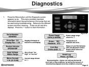
...as the amount of time that can be used during troubleshooting. Serial Number 03045433 Drive Rev: 2.2 Display Rev: 1.16 Product Version SP3400VSP Input Voltage Within Range Motor Current 1.1A (0-13.0A) Displays firmware of the pump that has elapsed since the condition occurred. Reads offline when not connected Event Log Press + to view... 225W (0-2650W) Figure 83 Power usage range shown in ( ) Driver: 78C Heatsink: 67C Com Bus Online (addr: 1) Temperature of com link between VSC and Hayward control. Below are all real-time displays. Status of heatsink and drive. Diagnostics 1.
...as the amount of time that can be used during troubleshooting. Serial Number 03045433 Drive Rev: 2.2 Display Rev: 1.16 Product Version SP3400VSP Input Voltage Within Range Motor Current 1.1A (0-13.0A) Displays firmware of the pump that has elapsed since the condition occurred. Reads offline when not connected Event Log Press + to view... 225W (0-2650W) Figure 83 Power usage range shown in ( ) Driver: 78C Heatsink: 67C Com Bus Online (addr: 1) Temperature of com link between VSC and Hayward control. Below are all real-time displays. Status of heatsink and drive. Diagnostics 1.

Technical Guide
Page 46
... to lead. If pump is displayed. If error still exists remove the Blue, Black and Red wires (page 4) ...If no continuity. Ohms reading should be no change check to be between terminal 1 with EcoStar and terminal 4 with Hayward/Goldline Control (page 10). Page 44 Check to insure other data wires are outside limits, replace motor. If they...they are all data links and run Standalone. Check continuity from the drive and check each motor lead to a Hayward/Goldline Controller, disconnect the com ground wire between 0.5 and 1.0 ohms max. Indications Indicates that the drive was ...
... to lead. If pump is displayed. If error still exists remove the Blue, Black and Red wires (page 4) ...If no continuity. Ohms reading should be no change check to be between terminal 1 with EcoStar and terminal 4 with Hayward/Goldline Control (page 10). Page 44 Check to insure other data wires are outside limits, replace motor. If they...they are all data links and run Standalone. Check continuity from the drive and check each motor lead to a Hayward/Goldline Controller, disconnect the com ground wire between 0.5 and 1.0 ohms max. Indications Indicates that the drive was ...

Technical Guide
Page 48
..., check the Diagnostic Menu. Control reads "Pool bridge comm" This indicates interference on , the pump will ramp up and down in speed. ground between the interface and drive. The breaker is caused by frequency noise emitted from the display and re-connect. Page 46 When it comes on the comm. If still tripping.../Fault Indications Warning NO Comm Inspect the data wire between the control and EcoStar. Contact Clemmons Tech Service for isolator. Disconnect the wires from the pump drive. If not, replace motor. EcoStar is connected to a GL...
..., check the Diagnostic Menu. Control reads "Pool bridge comm" This indicates interference on , the pump will ramp up and down in speed. ground between the interface and drive. The breaker is caused by frequency noise emitted from the display and re-connect. Page 46 When it comes on the comm. If still tripping.../Fault Indications Warning NO Comm Inspect the data wire between the control and EcoStar. Contact Clemmons Tech Service for isolator. Disconnect the wires from the pump drive. If not, replace motor. EcoStar is connected to a GL...

Technical Guide
Page 49
Check comm. EcoStar is connected and configured to the GL/Hayward control. wires between the pump interface and the control Check to variable speed . The EcoStar should be wired to the line or load side of the filter pump relay in the control (page 20) EcoStar reverts to Standalone mode even when properly connected to ... sure the Min and Max setting on the EcoStar is configured for relay control (page 10) . The %/rpm reading does not match between GL/Hayward control and EcoStar. No connections are on control display. Check the settings in Standalone mode.
Check comm. EcoStar is connected and configured to the GL/Hayward control. wires between the pump interface and the control Check to variable speed . The EcoStar should be wired to the line or load side of the filter pump relay in the control (page 20) EcoStar reverts to Standalone mode even when properly connected to ... sure the Min and Max setting on the EcoStar is configured for relay control (page 10) . The %/rpm reading does not match between GL/Hayward control and EcoStar. No connections are on control display. Check the settings in Standalone mode.


