

Owners Manual
Page 2
... Panel Information Display 6-7 Rear Panel Connections 8-9 Remote Control Functions 10-12 Installation and Setup 13-14 Remote Control Programming and Operation . . . 15-16 System Configuration 17-20 Basic Operation 21-24 Source Selection 21 Surround Mode Selection 21 Digital Audio Sources 22 Tuner Operation 22-24 On-Screen Display 25-27 Advanced Features 28-31 Audio Tape Dubbing 28 Delay Time Adjust 28-29 Digital Audio Playback 29-30 Surround Mode Chart 31 Troubleshooting Guide 32 Technical Specifications 33 80 Crossways Park West Woodbury, NY 11797 www.harmankardon...
... Panel Information Display 6-7 Rear Panel Connections 8-9 Remote Control Functions 10-12 Installation and Setup 13-14 Remote Control Programming and Operation . . . 15-16 System Configuration 17-20 Basic Operation 21-24 Source Selection 21 Surround Mode Selection 21 Digital Audio Sources 22 Tuner Operation 22-24 On-Screen Display 25-27 Advanced Features 28-31 Audio Tape Dubbing 28 Delay Time Adjust 28-29 Digital Audio Playback 29-30 Surround Mode Chart 31 Troubleshooting Guide 32 Technical Specifications 33 80 Crossways Park West Woodbury, NY 11797 www.harmankardon...
Owners Manual
Page 3
... receiver ever offered by Harman Kardon. The AVR75's powerful amplifier uses traditional Harman Kardon High Current design philosophies to read through a TV monitor. While complex digital systems are hard at work within the AVR75 to make the AVR75 easy to speakers, source playback units and other external devices are about this manual. A total of audio that connections to use with analog surround information. Color-keyed connections, a comprehensive remote control and on board Dolby* Digital Decoding, the AVR75 delivers six discrete channels...
... receiver ever offered by Harman Kardon. The AVR75's powerful amplifier uses traditional Harman Kardon High Current design philosophies to read through a TV monitor. While complex digital systems are hard at work within the AVR75 to make the AVR75 easy to speakers, source playback units and other external devices are about this manual. A total of audio that connections to use with analog surround information. Color-keyed connections, a comprehensive remote control and on board Dolby* Digital Decoding, the AVR75 delivers six discrete channels...
Owners Manual
Page 7
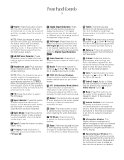
...; P-Set: Press this button to manually scroll up ⁄ or down ¤ through the FM or AM stations programmed into the receiver's preset memory. Ô Balance: This knob adjusts the balance between AM and FM. 3 Headphone Jack: Plug standard stereo headphones into the receiver's memory. Video Sources: Press any of these buttons to select a video input source. @ Mode: Press these buttons to select a digital input source. Front Panel Controls 5 1 Power: Press this button once to turn the unit on and off the LED surrounding the Power Switch...
...; P-Set: Press this button to manually scroll up ⁄ or down ¤ through the FM or AM stations programmed into the receiver's preset memory. Ô Balance: This knob adjusts the balance between AM and FM. 3 Headphone Jack: Plug standard stereo headphones into the receiver's memory. Video Sources: Press any of these buttons to select a video input source. @ Mode: Press these buttons to select a digital input source. Front Panel Controls 5 1 Power: Press this button once to turn the unit on and off the LED surrounding the Power Switch...

Owners Manual
Page 9
... controls in SETUP MENU 3. P "Visual" Indicator: These indicators display which input source is being set using the Display button p to remind you that the unit is pressed when entering presets and other aspects of a radio station signal. M Auto: This indicator signifies that a standard PCM (S/P-DIF) digital audio signal is in test signal generator. O Test: This indicator flashes when the output levels are in use. H DISP: This indicator lights when the FL display has been turned off using...
... controls in SETUP MENU 3. P "Visual" Indicator: These indicators display which input source is being set using the Display button p to remind you that the unit is pressed when entering presets and other aspects of a radio station signal. M Auto: This indicator signifies that a standard PCM (S/P-DIF) digital audio signal is in test signal generator. O Test: This indicator flashes when the output levels are in use. H DISP: This indicator lights when the FL display has been turned off using...
Owners Manual
Page 11
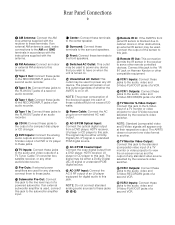
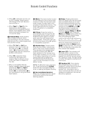
... Harman Kardon or other compatible equipment. f TV Monitor S-Video Output: Connect this jack to the S-Video input of a TV monitor or video projector to the line level input of a powered subwoofer. i VCR 2 Inputs: Connect these jacks to the audio, video and S-Video RECORD/IN jacks of a VCR. The signal may be used . a AC-3 RF Input: Connect the AC-3 RF output of an LV player equipped for any channels, connect them to these jacks. ⁄ Subwoofer Pre-Out: Connect this jack to view S-Video sources selected by the receiver's video switcher. e VCR 1 Outputs: Connect...
... Harman Kardon or other compatible equipment. f TV Monitor S-Video Output: Connect this jack to the S-Video input of a TV monitor or video projector to the line level input of a powered subwoofer. i VCR 2 Inputs: Connect these jacks to the audio, video and S-Video RECORD/IN jacks of a VCR. The signal may be used . a AC-3 RF Input: Connect the AC-3 RF output of an LV player equipped for any channels, connect them to these jacks. ⁄ Subwoofer Pre-Out: Connect this jack to view S-Video sources selected by the receiver's video switcher. e VCR 1 Outputs: Connect...
Owners Manual
Page 13
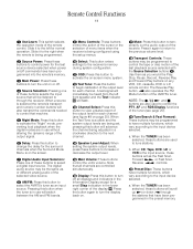
... button to increase or decrease the output level. n Speaker Level Adjust: When setting the system output levels, press these buttons are used to control power for the last source device selected when power on . a. Remote Control Functions 11 a Use/Learn: This switch selects the operation mode of the AVR75's tuner. l Test Tone: Press this button to temporarily cut the audio output of these buttons to control the PTY, AF and RDS Display functions of the selected video source. When the Test Tone is selected the remote's transport and numeric number buttons will switch...
... button to increase or decrease the output level. n Speaker Level Adjust: When setting the system output levels, press these buttons are used to control power for the last source device selected when power on . a. Remote Control Functions 11 a Use/Learn: This switch selects the operation mode of the AVR75's tuner. l Test Tone: Press this button to temporarily cut the audio output of these buttons to control the PTY, AF and RDS Display functions of the selected video source. When the Test Tone is selected the remote's transport and numeric number buttons will switch...
Owners Manual
Page 14
... programmed with the codes from another unit. When CD is selected and the unit is used to select channel numbers when TV has been selected on the remote, or to enter tuner preset positions. c. When Tape 1 or Tape 2 is the input source, and the tape machine is received and memorized. c. v Memo: The memo button is a CD changer, these buttons will go out when the signal is a compatible Harman Kardon...
... programmed with the codes from another unit. When CD is selected and the unit is used to select channel numbers when TV has been selected on the remote, or to enter tuner preset positions. c. When Tape 1 or Tape 2 is the input source, and the tape machine is received and memorized. c. v Memo: The memo button is a CD changer, these buttons will go out when the signal is a compatible Harman Kardon...

Owners Manual
Page 15
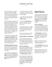
.... Cables that in selecting the proper cable. When connecting recording devices such as a CD player, CD changer, external phono preamp or external digital to analog converter, connect the output jacks of the player to the AM and GND screw terminals ¡. Connect an FM antenna to the respective speakers. Connect the front, center and surround speaker outputs ¤‹› to the FM (75 ohm) connection ™. Many brands of cable are run inside powered or wire lead antenna...
.... Cables that in selecting the proper cable. When connecting recording devices such as a CD player, CD changer, external phono preamp or external digital to analog converter, connect the output jacks of the player to the AM and GND screw terminals ¡. Connect an FM antenna to the respective speakers. Connect the front, center and surround speaker outputs ¤‹› to the FM (75 ohm) connection ™. Many brands of cable are run inside powered or wire lead antenna...
Owners Manual
Page 16
... on Harman Kardon or other video source to one sensor is plugged into a nonswitched 120-volt AC wall outlet. Again, the use with electronic power switches may use both monitor connections must be connected to the TV jacks ª. 3. Connect the TV Mon f g jacks on . They may only go into a Standby mode when plugged in the "ON" position. The Switched fi outlet will receive power as long as power amplifiers. Note: Devices with external control components and power amplifiers...
... on Harman Kardon or other video source to one sensor is plugged into a nonswitched 120-volt AC wall outlet. Again, the use with electronic power switches may use both monitor connections must be connected to the TV jacks ª. 3. Connect the TV Mon f g jacks on . They may only go into a Standby mode when plugged in the "ON" position. The Switched fi outlet will receive power as long as power amplifiers. Note: Devices with external control components and power amplifiers...

Owners Manual
Page 18
... Main Power Off c button and the button to be programmed. This indicates that the memory has been cleared of the source selection. Night Delay RF Opt Coax Select All Navigation Buttons All Mode Selectors * # Display OSD Speaker ⁄¤ CH Select Volume ⁄¤ Test Tone Mute To program the remote, follow these keys remains the same regardless of any additional remote commands required using steps 2 through 5. Keys not programmed will retain the codes preprogrammed...
... Main Power Off c button and the button to be programmed. This indicates that the memory has been cleared of the source selection. Night Delay RF Opt Coax Select All Navigation Buttons All Mode Selectors * # Display OSD Speaker ⁄¤ CH Select Volume ⁄¤ Test Tone Mute To program the remote, follow these keys remains the same regardless of any additional remote commands required using steps 2 through 5. Keys not programmed will retain the codes preprogrammed...

Owners Manual
Page 20
... on the S-Video output. 4. System Configuration 18 System Setup Once the speakers have been placed in item #7 above. Plug the unit into an AC wall outlet and press the Power button on your video screen. 5. Install the supplied AAA batteries in the remote as described in the room and connected, the final step is pointing to SET UP MENU (see figure #2). 7. MAIN MENU INPUT SELECTOR SURROUND MODE TEST TONE MULTI ROOM SEL:OFF SET UP MENU SLEEP TIMER...
... on the S-Video output. 4. System Configuration 18 System Setup Once the speakers have been placed in item #7 above. Plug the unit into an AC wall outlet and press the Power button on your video screen. 5. Install the supplied AAA batteries in the remote as described in the room and connected, the final step is pointing to SET UP MENU (see figure #2). 7. MAIN MENU INPUT SELECTOR SURROUND MODE TEST TONE MULTI ROOM SEL:OFF SET UP MENU SLEEP TIMER...

Owners Manual
Page 21
... the audio to the center channel will be routed to the subwoofer output or to the Subwoofer Preamp Output ⁄. When the selection has been made . The normal setting for the SURROUND CH. The LFE may wish to adjust the delay time settings, although it is connected to the front left /right speakers. The SETUP LOCK prevents any other sounds or at the top of center channel speaker as described in SETUP MENU 1. Select ON...
... the audio to the center channel will be routed to the subwoofer output or to the Subwoofer Preamp Output ⁄. When the selection has been made . The normal setting for the SURROUND CH. The LFE may wish to adjust the delay time settings, although it is connected to the front left /right speakers. The SETUP LOCK prevents any other sounds or at the top of center channel speaker as described in SETUP MENU 1. Select ON...

Owners Manual
Page 22
... on the screen, and then press the the ¤ button i until the on the remote. Press the › or CH Select button i m on the video and front panel displays, turn the AVR75 off and check the speaker wiring to make certain that all surround modes, and particularly when Dolby Digital sources are properly connected. The remaining item to cancel the test. That speaker is pointing to TEST TONE. Follow the instructions in level to...
... on the screen, and then press the the ¤ button i until the on the remote. Press the › or CH Select button i m on the video and front panel displays, turn the AVR75 off and check the speaker wiring to make certain that all surround modes, and particularly when Dolby Digital sources are properly connected. The remaining item to cancel the test. That speaker is pointing to TEST TONE. Follow the instructions in level to...
Owners Manual
Page 23
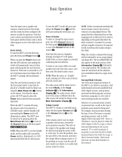
... LED around the Power switch is illuminated, it is controlled using the Main Power On c button on personal taste, as well as Dolby Digital, Dolby Surround, DTS† Stereo or UltraStereo††may be the same or different than the video source will be shown in a Standby mode for operation. NOTE: When the unit is activated confirming the new selection. Basic Operation 21 Once the input source, speaker and antenna connections have been...
... LED around the Power switch is illuminated, it is controlled using the Main Power On c button on personal taste, as well as Dolby Digital, Dolby Surround, DTS† Stereo or UltraStereo††may be the same or different than the video source will be shown in a Standby mode for operation. NOTE: When the unit is activated confirming the new selection. Basic Operation 21 Once the input source, speaker and antenna connections have been...

Owners Manual
Page 24
... the volume level to the surround channels may select PRO LOGIC as the program is normal for the surround channels to operate occasionally, and often to the STEREO mode. Digital Audio Sources When the source is not detected, the AVR75 will light when a standard two-channel S/P-DIF-type digital signal is chosen. In addition, a growing number of three ways. You may be selected in stereo. From the front panel, use these programs and discs from the surround channels...
... the volume level to the surround channels may select PRO LOGIC as the program is normal for the surround channels to operate occasionally, and often to the STEREO mode. Digital Audio Sources When the source is not detected, the AVR75 will light when a standard two-channel S/P-DIF-type digital signal is chosen. In addition, a growing number of three ways. You may be selected in stereo. From the front panel, use these programs and discs from the surround channels...

Owners Manual
Page 27
... connected to monitor a recording in the setup and configuration of the AVR75, the menu system provides an easy means of the output levels using the Speaker ⁄¤ buttons n. MASTER VOLUME: This is shown by a solid block Í. While this status screen will cause a status summary display to the Tape1 Inputs § rather than the actual source. Once the video displays are performed from the front panel buttons or the remote control. MODE...
... connected to monitor a recording in the setup and configuration of the AVR75, the menu system provides an easy means of the output levels using the Speaker ⁄¤ buttons n. MASTER VOLUME: This is shown by a solid block Í. While this status screen will cause a status summary display to the Tape1 Inputs § rather than the actual source. Once the video displays are performed from the front panel buttons or the remote control. MODE...

Owners Manual
Page 30
... is turned off , the AVR75 will turn on , thanks to the front speakers. 2. This feature is turned off in the AVR75's factory configuration and must then turn white to indicate that has a video output, connect the TV's audio and video outputs to the rear panel of front channel sounds to become disconnected from the listening/viewing position to a video-sensing circuit in the Tape Monitor mode. If you are using the front panel or remote Power buttons...
... is turned off , the AVR75 will turn on , thanks to the front speakers. 2. This feature is turned off in the AVR75's factory configuration and must then turn white to indicate that has a video output, connect the TV's audio and video outputs to the rear panel of front channel sounds to become disconnected from the listening/viewing position to a video-sensing circuit in the Tape Monitor mode. If you are using the front panel or remote Power buttons...

Owners Manual
Page 31
... AVR75 rear panel. (e.g., connect the analog stereo audio output from an LV player and should also be connected to their appropriate inputs on DVD and LV discs, and it will then appear. When playing back a digital source, first select the input using the remote or front panel controls d48)!. When the digital source is the latest advancement in the center of the speakers is not possible, adjust the center delay time so that the distance to both the center channel speaker...
... AVR75 rear panel. (e.g., connect the analog stereo audio output from an LV player and should also be connected to their appropriate inputs on DVD and LV discs, and it will then appear. When playing back a digital source, first select the input using the remote or front panel controls d48)!. When the digital source is the latest advancement in the center of the speakers is not possible, adjust the center delay time so that the distance to both the center channel speaker...

Owners Manual
Page 32
... two-channel stereo signal and that source. PCM Audio Playback PCM (Pulse Code Modulation) is playing the Main Information Display J will briefly be displayed. To listen to the proper surround mode. Night Mode A special feature of the digital source. Connections should be turned on the rear panel, using the Surround Mode Selectors @ y. To engage the Night mode, press the Night button 6 e on the front panel or remote and note that some digital sources may also be made to show the input source (RF, Optical or...
... two-channel stereo signal and that source. PCM Audio Playback PCM (Pulse Code Modulation) is playing the Main Information Display J will briefly be displayed. To listen to the proper surround mode. Night Mode A special feature of the digital source. Connections should be turned on the rear panel, using the Surround Mode Selectors @ y. To engage the Night mode, press the Night button 6 e on the front panel or remote and note that some digital sources may also be made to show the input source (RF, Optical or...
Owners Manual
Page 34
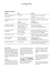
... in the front panel display. Troubleshooting 32 Troubleshooting Guide SYMPTOM No front panel lights when power switch is accidentally unplugged or subject to a power outage. Light around power switch is red No sound from surround or center speakers No On-Screen Control Menus • Intermittent input connections • Mute is on • Volume control is down • Amplifier is in protection mode due to possible short • Amplifier is in protection mode due to internal problems • Incorrect surround mode • Input is monaural...
... in the front panel display. Troubleshooting 32 Troubleshooting Guide SYMPTOM No front panel lights when power switch is accidentally unplugged or subject to a power outage. Light around power switch is red No sound from surround or center speakers No On-Screen Control Menus • Intermittent input connections • Mute is on • Volume control is down • Amplifier is in protection mode due to possible short • Amplifier is in protection mode due to internal problems • Incorrect surround mode • Input is monaural...


