
Manual
Page 1
MSH61DI LGA1155 socket motherboard for Intel® Core™ i3 / Core™ i5 Core™ i7 processors/ Intel® Pentium® series processors User's Manual Rev. 1001
MSH61DI LGA1155 socket motherboard for Intel® Core™ i3 / Core™ i5 Core™ i7 processors/ Intel® Pentium® series processors User's Manual Rev. 1001
Manual
Page 3
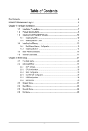
Table of Contents Box Contents...4 MSH61DI Motherboard Layout 5 Chapter 1 Hardware Installation 7 1-1 Installation Precautions 7 1-2 Product Specifications 8 1-3 Installing the CPU and CPU Cooler 10 1-3-1 Installing the CPU...10 1-3-2 Installing the CPU Cooler 12 1-4 Installing ...
Table of Contents Box Contents...4 MSH61DI Motherboard Layout 5 Chapter 1 Hardware Installation 7 1-1 Installation Precautions 7 1-2 Product Specifications 8 1-3 Installing the CPU and CPU Cooler 10 1-3-1 Installing the CPU...10 1-3-2 Installing the CPU Cooler 12 1-4 Installing ...

Manual
Page 4
The box contents are for reference only. - 4 - Box Contents MSH61DI motherboard Driver CD Two SATA cables I/O Shield • The box contents above are subject to change without notice. • The motherboard image is for reference only and the actual items shall depend on the product package you obtain.
The box contents are for reference only. - 4 - Box Contents MSH61DI motherboard Driver CD Two SATA cables I/O Shield • The box contents above are subject to change without notice. • The motherboard image is for reference only and the actual items shall depend on the product package you obtain.
Manual
Page 5
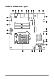
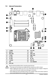
MSH61DI Motherboard Layout 123 4 5 6 78 9 10 11 28 27 12 26 29 30 13 25 14 24 15 16 17 18 23 22 21 20 19 - 5 -
MSH61DI Motherboard Layout 123 4 5 6 78 9 10 11 28 27 12 26 29 30 13 25 14 24 15 16 17 18 23 22 21 20 19 - 5 -
Manual
Page 7
... wrist strap, keep your hands dry and first touch a metal object to eliminate static electricity. • Prior to installing the motherboard, please have a problem related to the use of the product, please consult a certified computer technician. - 7 - Hardware Installation... ponents such as a result of electrostatic discharge (ESD). Chapter 1 Hardware Installation 1-1 Installation Precautions The motherboard contains numerous delicate electronic circuits and components which can lead to damage to system components as well as physical harm to the user....
... wrist strap, keep your hands dry and first touch a metal object to eliminate static electricity. • Prior to installing the motherboard, please have a problem related to the use of the product, please consult a certified computer technician. - 7 - Hardware Installation... ponents such as a result of electrostatic discharge (ESD). Chapter 1 Hardware Installation 1-1 Installation Precautions The motherboard contains numerous delicate electronic circuits and components which can lead to damage to system components as well as physical harm to the user....
Manual
Page 10
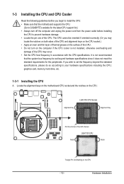
Locate the alignment keys on the motherboard CPU socket and the notches on the CPU - 10 - The CPU cannot be set the frequency beyond the standard specifications, please do so according to ... standard requirements for the latest CPU support list.) • Always turn on the computer if the CPU cooler is not recommended that the motherboard supports the CPU. (Go to GIGABYTE's website for the peripherals. 1-3 Installing the CPU and CPU Cooler Read the following guidelines before installing the CPU to prevent hardware damage...
Locate the alignment keys on the motherboard CPU socket and the notches on the CPU - 10 - The CPU cannot be set the frequency beyond the standard specifications, please do so according to ... standard requirements for the latest CPU support list.) • Always turn on the computer if the CPU cooler is not recommended that the motherboard supports the CPU. (Go to GIGABYTE's website for the peripherals. 1-3 Installing the CPU and CPU Cooler Read the following guidelines before installing the CPU to prevent hardware damage...
Manual
Page 11
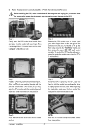
... one hand to hold the socket lever and use your thumb to lift up the front edge (next to correctly install the CPU into the motherboard CPU socket. Step 4: Once the CPU is under the shoulder screw. NOTE: Hold the CPU socket lever by the handle, not the lever base portion...
... one hand to hold the socket lever and use your thumb to lift up the front edge (next to correctly install the CPU into the motherboard CPU socket. Step 4: Once the CPU is under the shoulder screw. NOTE: Hold the CPU socket lever by the handle, not the lever base portion...
Manual
Page 12
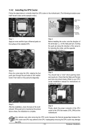
... the Male Push Pin Male Push Pin The Top of Female Push Pin Female Push Pin Step 1: Apply an even and thin layer of the motherboard. Use extreme care when removing the CPU cooler because the thermal grease/tape between the CPU cooler and CPU may damage the CPU. - 12 - Check... CPU cooler installation manual for installing it..) Step 3: Place the cooler atop the CPU, aligning the four push pins through the pin holes on the motherboard. Step 4: You should hear a "click" when pushing down on the surface of the CPU cooler to the CPU fan header (CPU_FAN) on the...
... the Male Push Pin Male Push Pin The Top of Female Push Pin Female Push Pin Step 1: Apply an even and thin layer of the motherboard. Use extreme care when removing the CPU cooler because the thermal grease/tape between the CPU cooler and CPU may damage the CPU. - 12 - Check... CPU cooler installation manual for installing it..) Step 3: Place the cooler atop the CPU, aligning the four push pins through the pin holes on the motherboard. Step 4: You should hear a "click" when pushing down on the surface of the CPU cooler to the CPU fan header (CPU_FAN) on the...
Manual
Page 13
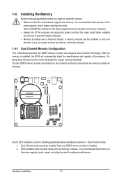
... from the power outlet before installing the memory in only one DDR3 memory module is recommended that the motherboard supports the memory. Hardware Installation - 13 - The two DDR3 memory sockets are unable to GIGABYTE's website for optimum performance. Enabling Dual Channel memory mode will automatically detect the specifications and capacity of the...
... from the power outlet before installing the memory in only one DDR3 memory module is recommended that the motherboard supports the memory. Hardware Installation - 13 - The two DDR3 memory sockets are unable to GIGABYTE's website for optimum performance. Enabling Dual Channel memory mode will automatically detect the specifications and capacity of the...
Manual
Page 14
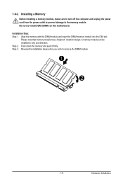
... module and insert the DIMM memory module into the DIM slot. Step 2. Reverse the installation steps when you wish to install DDR3 DIMMs on this motherboard. 1-4-2 Installing a Memory Before installing a memory module, make sure to turn off the computer and unplug the power cord from the power outlet to prevent damage...
... module and insert the DIMM memory module into the DIM slot. Step 2. Reverse the installation steps when you wish to install DDR3 DIMMs on this motherboard. 1-4-2 Installing a Memory Before installing a memory module, make sure to turn off the computer and unplug the power cord from the power outlet to prevent damage...

Manual
Page 16
Do not rock it side to side to a back panel connector, first remove the cable from your device and then remove it from the motherboard. • When removing the cable, pull it straight out from the connector. Connection/ Speed LED Activity LED LAN Port Connection/Speed LED: State Orange Green ...
Do not rock it side to side to a back panel connector, first remove the cable from your device and then remove it from the motherboard. • When removing the cable, pull it straight out from the connector. Connection/ Speed LED Activity LED LAN Port Connection/Speed LED: State Orange Green ...
Manual
Page 17
..., make sure your devices are compliant with the connectors you wish to connect. • Before installing the devices, be sure to the connector on the motherboard. - 17 -
..., make sure your devices are compliant with the connectors you wish to connect. • Before installing the devices, be sure to the connector on the motherboard. - 17 -

Manual
Page 21
...LCD TVs use this header. The headers conform to this interface internally. Hardware Installation Incorrect connection between the module connector and the motherboard header will be present on both of the front and back panel audio connections simultaneously. • Some chassis provide a front ...contact the chassis manufacturer. 8) FPD (Flat Panel Display Headers) Flat Panel Display (FPD)is a high-speed interface connecting the output of the motherboard header. Pin No. 7) F_AUDIO (Front Panel Audio Header) The front panel audio header supports Intel High Definition audio (HD) and AC'...
...LCD TVs use this header. The headers conform to this interface internally. Hardware Installation Incorrect connection between the module connector and the motherboard header will be present on both of the front and back panel audio connections simultaneously. • Some chassis provide a front ...contact the chassis manufacturer. 8) FPD (Flat Panel Display Headers) Flat Panel Display (FPD)is a high-speed interface connecting the output of the motherboard header. Pin No. 7) F_AUDIO (Front Panel Audio Header) The front panel audio header supports Intel High Definition audio (HD) and AC'...
Manual
Page 22
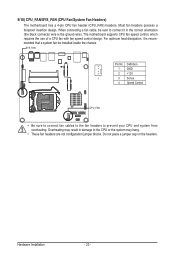
9/10) CPU_FAN/SYS_FAN (CPU Fan/System Fan Headers) The motherboard has a 4-pin CPU fan header (CPU_FAN) headers. For optimum heat dissipation, it is recommended that a system fan be sure to connect it in damage to ... place a jumper cap on the headers. Overheating may result in the correct orientation (the black connector wire is the ground wire). Hardware Installation - 22 - The motherboard supports CPU fan speed control, which requires the use of a CPU fan with fan speed control design. Definition 1 GND 2 +12V 1 3 Sense 4 Speed Control CPU_FAN •...
9/10) CPU_FAN/SYS_FAN (CPU Fan/System Fan Headers) The motherboard has a 4-pin CPU fan header (CPU_FAN) headers. For optimum heat dissipation, it is recommended that a system fan be sure to connect it in damage to ... place a jumper cap on the headers. Overheating may result in the correct orientation (the black connector wire is the ground wire). Hardware Installation - 22 - The motherboard supports CPU fan speed control, which requires the use of a CPU fan with fan speed control design. Definition 1 GND 2 +12V 1 3 Sense 4 Speed Control CPU_FAN •...
Manual
Page 26
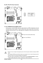
... CMOS values, place a jumper cap on your computer and unplug the power cord from the jumper. Failure to do so may cause damage to the motherboard. • After system restart, go to BIOS Setup to load factory defaults (select Load Optimized Defaults) or manually configure the BIOS settings (refer to factory...
... CMOS values, place a jumper cap on your computer and unplug the power cord from the jumper. Failure to do so may cause damage to the motherboard. • After system restart, go to BIOS Setup to load factory defaults (select Load Optimized Defaults) or manually configure the BIOS settings (refer to factory...
Manual
Page 27
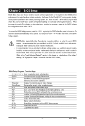
... the main menu of the BIOS Setup program. • BIOS flashing is potentially risky, if you do it is turned off, the battery on the motherboard. To flash the BIOS, do not encounter problems of using the current BIOS version, it with caution. When the power is recommended that you need... Help block on . BIOS Setup Chapter 2 BIOS Setup BIOS (Basic Input and Output System) records hardware parameters of the system in the CMOS on the motherboard supplies the necessary power to the CMOS to keep the configuration values in the CMOS. If this occurs, try to clear the CMOS values and...
... the main menu of the BIOS Setup program. • BIOS flashing is potentially risky, if you do it is turned off, the battery on the motherboard. To flash the BIOS, do not encounter problems of using the current BIOS version, it with caution. When the power is recommended that you need... Help block on . BIOS Setup Chapter 2 BIOS Setup BIOS (Basic Input and Output System) records hardware parameters of the system in the CMOS on the motherboard supplies the necessary power to the CMOS to keep the configuration values in the CMOS. If this occurs, try to clear the CMOS values and...


