Manual
Page 10
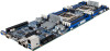
... Byte 1 = 00h : Command Completed Normally Byte 2 = 01h : Copying To Scratch Byte 3 = 00h : Update Progress (If byte 2 is 06, this data is available.) e.g. ipmitool -H 10.1.27.150 -U admin -P password raw 0x2e 0x20 0x0a 0x3c 0x00 0x0e 0x00 0x00 0x0a 0x01 0x1b 0x34 0x69 0x6d 0x61 0x67 0x65... 0x2e 0x52 0x42 0x55 Command format: raw : 0x69 0x6d 0x61 0x67 0x65 0x2e 0x52 0x42 0x55 = image.RBU [5] Check upload status e.g. GIGA -BYTE TECHNOLOGY CO., LTD. [4] Upload "image.RBU" through TFTP service...
... Byte 1 = 00h : Command Completed Normally Byte 2 = 01h : Copying To Scratch Byte 3 = 00h : Update Progress (If byte 2 is 06, this data is available.) e.g. ipmitool -H 10.1.27.150 -U admin -P password raw 0x2e 0x20 0x0a 0x3c 0x00 0x0e 0x00 0x00 0x0a 0x01 0x1b 0x34 0x69 0x6d 0x61 0x67 0x65... 0x2e 0x52 0x42 0x55 Command format: raw : 0x69 0x6d 0x61 0x67 0x65 0x2e 0x52 0x42 0x55 = image.RBU [5] Check upload status e.g. GIGA -BYTE TECHNOLOGY CO., LTD. [4] Upload "image.RBU" through TFTP service...
Manual
Page 3
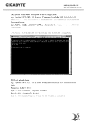
... 1-5-4 pgadminIII Installation Procedure (Optional 15 1-5-5 Login Gigabyte Server Management Console 16 Chapter 2 Gigabyte Server Management Console 17 2-1 Overview...17 2-2 Enter Gigabyte Server Management Console 18 2-2-1 Node Info...18 2-2-1-1 Node ID...20 Power Consumption...20 SEL ...21 Node Detail...21 Chassis ...22 Sensor ...23 Trap IP Destination List...24 Platform Events...25 BMC Update...26 BIOS Update...26 Power Limit...27 IP Configuration...27 CPU Utilization...27...
... 1-5-4 pgadminIII Installation Procedure (Optional 15 1-5-5 Login Gigabyte Server Management Console 16 Chapter 2 Gigabyte Server Management Console 17 2-1 Overview...17 2-2 Enter Gigabyte Server Management Console 18 2-2-1 Node Info...18 2-2-1-1 Node ID...20 Power Consumption...20 SEL ...21 Node Detail...21 Chassis ...22 Sensor ...23 Trap IP Destination List...24 Platform Events...25 BMC Update...26 BIOS Update...26 Power Limit...27 IP Configuration...27 CPU Utilization...27...
Manual
Page 3
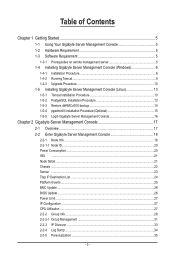
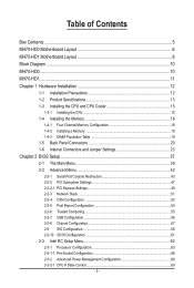
......5 MH70-HD0 Motherboard Layout 6 MH70-HD1 Motherboard Layout 8 Block Diagram...10 MH70-HD0...10 MH70-HD1...11 Chapter 1 Hardware Installation 12 1-1 Installation Precautions 12 1-2 Product Specifications 13 1-3 Installing the CPU and CPU Cooler 15 1-3-1 Installing the CPU...15 1-4 Installing the Memory 18 1-4-1 Four Channel Memory Configuration 18 1-4-2 Installing a Memory 19 1-4-3 DIMM Population Table 19 1-5 Back Panel Connectors 20 1-6 Internal Connectors and Jumper Settings 23 Chapter 2 BIOS Setup 37 2-1 The Main Menu 39 2-2 Advanced Menu 42 2-2-1 Serial Port Console...
......5 MH70-HD0 Motherboard Layout 6 MH70-HD1 Motherboard Layout 8 Block Diagram...10 MH70-HD0...10 MH70-HD1...11 Chapter 1 Hardware Installation 12 1-1 Installation Precautions 12 1-2 Product Specifications 13 1-3 Installing the CPU and CPU Cooler 15 1-3-1 Installing the CPU...15 1-4 Installing the Memory 18 1-4-1 Four Channel Memory Configuration 18 1-4-2 Installing a Memory 19 1-4-3 DIMM Population Table 19 1-5 Back Panel Connectors 20 1-6 Internal Connectors and Jumper Settings 23 Chapter 2 BIOS Setup 37 2-1 The Main Menu 39 2-2 Advanced Menu 42 2-2-1 Serial Port Console...

Manual
Page 6
... Code Description 1 VGA_1 Rear VGA port 2 F_VGA1 Front VGA header 3 COM1 Rear serial port 4 COM2 5 SW_PWR1 6 SW_ID 7 SW_RST_NMI Front serial port header Power button/LED ID switch button Reset button (top)/NMI button (buttom) 8 LED_STA System status LED 9 LED_LAN LAN1 (buttom)/LAN2 (top) Active/Link LEDs 10 QSFP_1 QSFP LAN port 11 USB3_LAN1 BMC management LAN port (top)/USB 3.0 ports (buttom) 12 SATA0/SATA1/SATA2/SATA3/ SATA 6Gb/s connectors SATA4/SATA5 13 BAT1 Battery socket 14 SATA_SGP1 SATA SGPIO header 15 DIMM_P0_A0 Channel 1 slot...
... Code Description 1 VGA_1 Rear VGA port 2 F_VGA1 Front VGA header 3 COM1 Rear serial port 4 COM2 5 SW_PWR1 6 SW_ID 7 SW_RST_NMI Front serial port header Power button/LED ID switch button Reset button (top)/NMI button (buttom) 8 LED_STA System status LED 9 LED_LAN LAN1 (buttom)/LAN2 (top) Active/Link LEDs 10 QSFP_1 QSFP LAN port 11 USB3_LAN1 BMC management LAN port (top)/USB 3.0 ports (buttom) 12 SATA0/SATA1/SATA2/SATA3/ SATA 6Gb/s connectors SATA4/SATA5 13 BAT1 Battery socket 14 SATA_SGP1 SATA SGPIO header 15 DIMM_P0_A0 Channel 1 slot...

Manual
Page 7
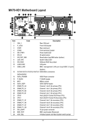
...18 pin power connector Channel 1 slot 0 (for secondary CPU) Channel 1 slot 1 (for secondary CPU) Channel 2 slot 0 (for secondary CPU) Channel 2 slot 1 (for secondary CPU) Channel 3 slot 0 (for primary CPU) Channel 3 slot 1 (for primary CPU) Channel 4 slot 0 (for primary CPU) Channel 4 slot 1 (for primary CPU) BMC SGPIO header USB 3.0 header TPM module connector PCI-E slot 1 (x16 slot/Running at x16) IPMB connector BMC firmware readiness LED Software RAID Key jumper Clear CMOS jumper PCI-E x8 slot (for Mezzanine card/Proprietary slot/ Running at x8) ME update jumper Clearing Supervisor Password...
...18 pin power connector Channel 1 slot 0 (for secondary CPU) Channel 1 slot 1 (for secondary CPU) Channel 2 slot 0 (for secondary CPU) Channel 2 slot 1 (for secondary CPU) Channel 3 slot 0 (for primary CPU) Channel 3 slot 1 (for primary CPU) Channel 4 slot 0 (for primary CPU) Channel 4 slot 1 (for primary CPU) BMC SGPIO header USB 3.0 header TPM module connector PCI-E slot 1 (x16 slot/Running at x16) IPMB connector BMC firmware readiness LED Software RAID Key jumper Clear CMOS jumper PCI-E x8 slot (for Mezzanine card/Proprietary slot/ Running at x8) ME update jumper Clearing Supervisor Password...
Manual
Page 8
...2 F_VGA1 Code Description Rear VGA port Front VGA header 3 COM1 Rear serial port 4 COM2 Front serial port header 5 SW_PWR1 Power button/LED 6 SW_ID ID switch button 7 SW_RST_NMI Reset button (top)/NMI button (buttom) 8 LED_STA System status LED 9 SW_RAID Software RAID Key jumper 10 LAN1/LAN2 LAN ports 11 USB3_LAN1 BMC management LAN port (top)/USB 3.0 ports (buttom) 12 SATA0/SATA1/SATA2/SATA3/ SATA 6Gb/s connectors SATA4/SATA5 13 SATA_POWER 14 F_MLAN 15 BAT1 SATA Power connector F_MLAN header Battery socket 16 SATA_SGP1 SATA SGPIO header 17 DIMM_P0_A0 Channel 1 slot...
...2 F_VGA1 Code Description Rear VGA port Front VGA header 3 COM1 Rear serial port 4 COM2 Front serial port header 5 SW_PWR1 Power button/LED 6 SW_ID ID switch button 7 SW_RST_NMI Reset button (top)/NMI button (buttom) 8 LED_STA System status LED 9 SW_RAID Software RAID Key jumper 10 LAN1/LAN2 LAN ports 11 USB3_LAN1 BMC management LAN port (top)/USB 3.0 ports (buttom) 12 SATA0/SATA1/SATA2/SATA3/ SATA 6Gb/s connectors SATA4/SATA5 13 SATA_POWER 14 F_MLAN 15 BAT1 SATA Power connector F_MLAN header Battery socket 16 SATA_SGP1 SATA SGPIO header 17 DIMM_P0_A0 Channel 1 slot...
Manual
Page 13
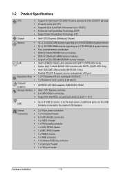
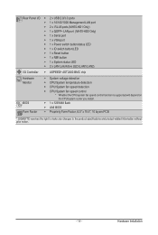
... LAN controller (MH70-HD1 Only) Realtek RTL8211E supports server management LAN port 1 x PCI Express x16 slot, running at x16 (Gen3) 1 x Mezzanine Card, running at x8 (Gen3) ASPEED® AST2400 supports 16MB DDR3 VRAM Intel® C612 Express controller 6 x SATA3 6Gb/s connectors Support for Intel RSTe 4.0 with SATA RAID 0, RAID 1, 10, 5 USB ŠŠ Up to 4 USB 3.0 ports ( 2 on the back panel, 2 additional ports via the USB brackets connected to the internal USB headers) Internal Connectors ŠŠ 2 x 18-pin power connectors ŠŠ 1 x Front panel header...
... LAN controller (MH70-HD1 Only) Realtek RTL8211E supports server management LAN port 1 x PCI Express x16 slot, running at x16 (Gen3) 1 x Mezzanine Card, running at x8 (Gen3) ASPEED® AST2400 supports 16MB DDR3 VRAM Intel® C612 Express controller 6 x SATA3 6Gb/s connectors Support for Intel RSTe 4.0 with SATA RAID 0, RAID 1, 10, 5 USB ŠŠ Up to 4 USB 3.0 ports ( 2 on the back panel, 2 additional ports via the USB brackets connected to the internal USB headers) Internal Connectors ŠŠ 2 x 18-pin power connectors ŠŠ 1 x Front panel header...
Manual
Page 14
...-45 ports (MH70-HD1 Only) ŠŠ 1 x QSFP+ LAN port (MH70-HD0 Only) ŠŠ 1 x Serial port ŠŠ 1 x VGA port ŠŠ 1 x Power switch button/status LED ŠŠ 1 x ID switch button/LED ŠŠ 1 x Reset button ŠŠ 1 x NMI button ŠŠ 1 x System status LED ŠŠ 2 x LAN Link/Active LED (LAN1/LAN2) ŠŠ ASPEED® AST2400 BMC chip ŠŠ System voltage detection ŠŠ CPU/System temperature detection ŠŠ CPU/System fan speed detection...
...-45 ports (MH70-HD1 Only) ŠŠ 1 x QSFP+ LAN port (MH70-HD0 Only) ŠŠ 1 x Serial port ŠŠ 1 x VGA port ŠŠ 1 x Power switch button/status LED ŠŠ 1 x ID switch button/LED ŠŠ 1 x Reset button ŠŠ 1 x NMI button ŠŠ 1 x System status LED ŠŠ 2 x LAN Link/Active LED (LAN1/LAN2) ŠŠ ASPEED® AST2400 BMC chip ŠŠ System voltage detection ŠŠ CPU/System temperature detection ŠŠ CPU/System fan speed detection...

Manual
Page 18
... BIOS will be enabled if only one direction. When enabling Four Channel mode with two or four memory modules, it is recommended that memory of the same capacity, brand, speed, and chips be used . • Always turn off the computer and unplug the power cord from the power outlet before installing the memory to insert the memory, switch the direction. 1-4-1 Four Channel Memory Configuration This motherboard provides sixteen DDR4 memory sockets and supports Four Channel Technology. A memory...
... BIOS will be enabled if only one direction. When enabling Four Channel mode with two or four memory modules, it is recommended that memory of the same capacity, brand, speed, and chips be used . • Always turn off the computer and unplug the power cord from the power outlet before installing the memory to insert the memory, switch the direction. 1-4-1 Four Channel Memory Configuration This motherboard provides sixteen DDR4 memory sockets and supports Four Channel Technology. A memory...
Manual
Page 20
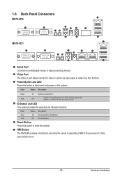
Video Port The video in port allows connect to video loop thru function. Color Status Description Green On System is in , which can also apply to video in ACPI S4 state (hibernate mode) ID Button and LED This button provides the selected unit idfication function. Reset Button Press this button to reset the system. Hardware Installation N/A Off No identification. Power Button and LED Press this button to hard reset and power on . 1-5 Back Panel Connectors MH70-HD0 MH70-HD1 Serial Port Connects to...
Video Port The video in port allows connect to video loop thru function. Color Status Description Green On System is in , which can also apply to video in ACPI S4 state (hibernate mode) ID Button and LED This button provides the selected unit idfication function. Reset Button Press this button to reset the system. Hardware Installation N/A Off No identification. Power Button and LED Press this button to hard reset and power on . 1-5 Back Panel Connectors MH70-HD0 MH70-HD1 Serial Port Connects to...
Manual
Page 32
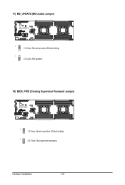
17) ME_UPDATE (ME Update Jumper) ME_UPDATE 1 1-2 Close: Normal operation (Default setting) 1 2-3 Close: ME updated. 18) BIOS_PWD (Clearing Supervisor Password Jumper) BIOS_PWD 1 1-2 Close: Normal operation. (Default setting) 1 2-3 Close: Skip supervisor password. Hardware Installation - 32 -
17) ME_UPDATE (ME Update Jumper) ME_UPDATE 1 1-2 Close: Normal operation (Default setting) 1 2-3 Close: ME updated. 18) BIOS_PWD (Clearing Supervisor Password Jumper) BIOS_PWD 1 1-2 Close: Normal operation. (Default setting) 1 2-3 Close: Skip supervisor password. Hardware Installation - 32 -
Manual
Page 33
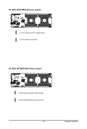
19) BIOS_RCVR (BIOS Recovery Jumper) BIOS_RCVR 1 1-2 Close: Normal operation. (Default setting) 1 2-3 Close: BIOS recovery mode. 20) BIOS_WP (BIOS Write Protect Jumper) BIOS_WP 1 1-2 Close: Normal operation. (Default setting) 1 2-3 Close: Enable BIOS write protect function. - 33 - Hardware Installation
19) BIOS_RCVR (BIOS Recovery Jumper) BIOS_RCVR 1 1-2 Close: Normal operation. (Default setting) 1 2-3 Close: BIOS recovery mode. 20) BIOS_WP (BIOS Write Protect Jumper) BIOS_WP 1 1-2 Close: Normal operation. (Default setting) 1 2-3 Close: Enable BIOS write protect function. - 33 - Hardware Installation
Manual
Page 37
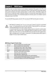
...'t flash the BIOS. To flash the BIOS, do not encounter problems of using the current BIOS version, it with caution. If this occurs, try to clear the CMOS values and reset the board to default values. (Refer to the Exit section in this chapter or introductions of the battery/clearing CMOS jumper in Chapter 1 for the current submenus Save all the changes and exit the BIOS Setup program - 37 - BIOS includes a BIOS Setup...
...'t flash the BIOS. To flash the BIOS, do not encounter problems of using the current BIOS version, it with caution. If this occurs, try to clear the CMOS values and reset the board to default values. (Refer to the Exit section in this chapter or introductions of the battery/clearing CMOS jumper in Chapter 1 for the current submenus Save all the changes and exit the BIOS Setup program - 37 - BIOS includes a BIOS Setup...
Manual
Page 45
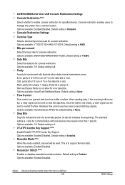
... LAN Console Redirection Settings Console Redirection (Note) Select whether to enable console redirection for console redirection. Data Bits Select the data bits for specified device. Mark and Space Parity do not allow for console redirection. Hardware flow control uses two wires to send start the flow. Options available: 1/2. Default setting is to be send. This is Enabled. Options available: Enabled/Disabled. (Note) Advanced items prompt when this mode enabled...
... LAN Console Redirection Settings Console Redirection (Note) Select whether to enable console redirection for console redirection. Data Bits Select the data bits for specified device. Mark and Space Parity do not allow for console redirection. Hardware flow control uses two wires to send start the flow. Options available: 1/2. Default setting is to be send. This is Enabled. Options available: Enabled/Disabled. (Note) Advanced items prompt when this mode enabled...

Manual
Page 47
... Snoop Enable/Disable VGA Palette Tegisters Snooping. Options available: Enabled/Disabled. Options available: Enabled/Disabled. Default setting is Enabled. Default setting is Disabled. - 47 - Options available: 32 PCI Bus Clocks/64 PCI Bus Clocks/96 PCI Bus Clocks/128 PCI Bus Clocks/160 PCI Bus Clocks/192 PCI Bus Clocks/224 PCI Bus Clocks/248 PCI Bus Clocks/. Default setting is Disabled. Options available: Enabled/Disabled. Default setting is 32 PCI Bus Clocks. 2-2-2 PCI Subsystem Settings PCI Express Slot #1/#2 I /O ROM Enable/Disable onboard LAN devices and...
... Snoop Enable/Disable VGA Palette Tegisters Snooping. Options available: Enabled/Disabled. Options available: Enabled/Disabled. Default setting is Enabled. Default setting is Disabled. - 47 - Options available: 32 PCI Bus Clocks/64 PCI Bus Clocks/96 PCI Bus Clocks/128 PCI Bus Clocks/160 PCI Bus Clocks/192 PCI Bus Clocks/224 PCI Bus Clocks/248 PCI Bus Clocks/. Default setting is Disabled. Options available: Enabled/Disabled. Default setting is 32 PCI Bus Clocks. 2-2-2 PCI Subsystem Settings PCI Express Slot #1/#2 I /O ROM Enable/Disable onboard LAN devices and...

Manual
Page 49
... Enable/Disable PCI Express Device No Snoop option. Press / keys to select the value. 2-2-2-1 PCI Express Settings PCI Express Device Register Settings Relaxed Ordering Enable/DIsable PCI Express Device Relaxed Ordering feature. Options available: Enabled/Disabled. BIOS Setup Maximum Playload Set maximum playload for PCI Express Device or allow generation of Retry Attempts software wil take to use 8-bit Tag field as a requester. Options available: Auto/128 Bytes/256 Bytes/512 Bytes/1024 Bytes/2048 Bytes/4096 Bytes. Options available: Enabled/Disabled. Default setting is enabled...
... Enable/Disable PCI Express Device No Snoop option. Press / keys to select the value. 2-2-2-1 PCI Express Settings PCI Express Device Register Settings Relaxed Ordering Enable/DIsable PCI Express Device Relaxed Ordering feature. Options available: Enabled/Disabled. BIOS Setup Maximum Playload Set maximum playload for PCI Express Device or allow generation of Retry Attempts software wil take to use 8-bit Tag field as a requester. Options available: Auto/128 Bytes/256 Bytes/512 Bytes/1024 Bytes/2048 Bytes/4096 Bytes. Options available: Enabled/Disabled. Default setting is enabled...

Manual
Page 64
... allows a single processor to execute two or more vulnerable to enable the speculative prefetch unit of advanced items. Processor Socket/Processor ID/Processor Frequency/Processor Max Raito/ Processor Min Raio/Microcode Revision/L1 Cache RAM/L2 Cache RAM/L3 Cache RAM/ Processor 0/1Version Displays the technical specifications for the installed processor. BIOS Setup - 64 - Options available: Enabled/Disabled. Enable Intel TXT Support Enable/Disable Intel Trusted Execution Technology support function. Processor Configuration Pre-Socket Configuration Press [Enter] for configuration of the...
... allows a single processor to execute two or more vulnerable to enable the speculative prefetch unit of advanced items. Processor Socket/Processor ID/Processor Frequency/Processor Max Raito/ Processor Min Raio/Microcode Revision/L1 Cache RAM/L2 Cache RAM/L3 Cache RAM/ Processor 0/1Version Displays the technical specifications for the installed processor. BIOS Setup - 64 - Options available: Enabled/Disabled. Enable Intel TXT Support Enable/Disable Intel Trusted Execution Technology support function. Processor Configuration Pre-Socket Configuration Press [Enter] for configuration of the...

Manual
Page 80
Options available: Disable/Mirror/Lockstep Mode. Default setting is Disabled. Default setting is Disabled. Lockstep x4 DIMMs Options available: Auto/Disabled/Enabled. BIOS Setup - 80 - Enabling Sparing and Mirroring is set to increase or decrease the desired values. When this item is not supported. Correctable Error Threshold Press / keys to enabled, Sparing will be selected. Default setting is Disabled. Lockstep Rank Sparing Options available: Auto/Disabled/Enabled. 2-3-5-4 Memory RAS Configuration RAS Mode Enable/Disable RAS modes.
Options available: Disable/Mirror/Lockstep Mode. Default setting is Disabled. Default setting is Disabled. Lockstep x4 DIMMs Options available: Auto/Disabled/Enabled. BIOS Setup - 80 - Enabling Sparing and Mirroring is set to increase or decrease the desired values. When this item is not supported. Correctable Error Threshold Press / keys to enabled, Sparing will be selected. Default setting is Disabled. Lockstep Rank Sparing Options available: Auto/Disabled/Enabled. 2-3-5-4 Memory RAS Configuration RAS Mode Enable/Disable RAS modes.

Manual
Page 87
... on chip SATA type. Default setting is Disabled. SATA RSTe Boot Info(Note 1) Enable/Disable SATA RSTe Boot Information. When SATA Type is Enabled. Default setting is set to IDE, the SATA controller disables its AHCI functionality. You will be access the RAID setup utility at boot time. RAID Mode: When set to access RAID setup utility. Options available: Enabled/Disabled. SATA Mode options(Note 2) Press [Enter] for configuration of advanced items. (Note 1) Only Supported When HDD is in AHCI or RAID Mode. - 87 - This is in RAID Mode. (Note 2) Only Supported When HDD...
... on chip SATA type. Default setting is Disabled. SATA RSTe Boot Info(Note 1) Enable/Disable SATA RSTe Boot Information. When SATA Type is Enabled. Default setting is set to IDE, the SATA controller disables its AHCI functionality. You will be access the RAID setup utility at boot time. RAID Mode: When set to access RAID setup utility. Options available: Enabled/Disabled. SATA Mode options(Note 2) Press [Enter] for configuration of advanced items. (Note 1) Only Supported When HDD is in AHCI or RAID Mode. - 87 - This is in RAID Mode. (Note 2) Only Supported When HDD...
Manual
Page 95
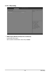
2-3-10-1 Whea Setting WHEA Support (Windows Hardware Error Architecture) Enable/Disable WHEA Support. Default setting is Enabled. - 95 - Options available: Enabled/Disabled. BIOS Setup
2-3-10-1 Whea Setting WHEA Support (Windows Hardware Error Architecture) Enable/Disable WHEA Support. Default setting is Enabled. - 95 - Options available: Enabled/Disabled. BIOS Setup


