
Manual
Page 1
... enable the Intel Smart Response Technology • The Intel Smart Response Technology requires a computer system with an Intel Z68 Chipset-based motherboard and an Intel Core series CPU. • The operating system must be installed to enter BIOS Setup during the POST (Power-... - 1 - Installing a conventional SATA hard disk and a solid-state drive (SSD): Besides the conventional SATA disk, you will be used for your motherboard. Then save changes and exit BIOS Setup. Installing a conventional SATA hard disk and a solid-state drive (SSD) 2. Enabling RAID mode in BIOS Setup...
... enable the Intel Smart Response Technology • The Intel Smart Response Technology requires a computer system with an Intel Z68 Chipset-based motherboard and an Intel Core series CPU. • The operating system must be installed to enter BIOS Setup during the POST (Power-... - 1 - Installing a conventional SATA hard disk and a solid-state drive (SSD): Besides the conventional SATA disk, you will be used for your motherboard. Then save changes and exit BIOS Setup. Installing a conventional SATA hard disk and a solid-state drive (SSD) 2. Enabling RAID mode in BIOS Setup...

Manual
Page 2
... the steps above . 4. English 3. Make sure the Intel Rapid Storage Technology driver version is complete, use the "Xpress Install" function of the motherboard driver disk to open the Intel Rapid Storage Technology utility. - 2 - After the installation is 10.5 or above and restarting your system, fi...;nd the IRST icon in the notification area and double-click it to install all motherboard drivers, including the Intel Rapid Storage Technology driver. Installing the operating system and drivers to the SATA disk: After setting the BIOS...
... the steps above . 4. English 3. Make sure the Intel Rapid Storage Technology driver version is complete, use the "Xpress Install" function of the motherboard driver disk to open the Intel Rapid Storage Technology utility. - 2 - After the installation is 10.5 or above and restarting your system, fi...;nd the IRST icon in the notification area and double-click it to install all motherboard drivers, including the Intel Rapid Storage Technology driver. Installing the operating system and drivers to the SATA disk: After setting the BIOS...
User Manual
Page 2
Motherboard GA-Z68XP-UD4 May 31, 2011 Motherboard GA-Z68XP-UD4 May 31, 2011
Motherboard GA-Z68XP-UD4 May 31, 2011 Motherboard GA-Z68XP-UD4 May 31, 2011

User Manual
Page 3
... on our website at: http://www.gigabyte.com Identifying Your Motherboard Revision The revision number on your motherboard revision before updating motherboard BIOS, drivers, or when looking for technical information. For example, "REV: 1.0" means the revision of GIGABYTE. Changes to the specifications and features in... this manual is protected by copyright laws and is the property of the motherboard is 1.0. No part of the product, read the Quick Installation Guide...
... on our website at: http://www.gigabyte.com Identifying Your Motherboard Revision The revision number on your motherboard revision before updating motherboard BIOS, drivers, or when looking for technical information. For example, "REV: 1.0" means the revision of GIGABYTE. Changes to the specifications and features in... this manual is protected by copyright laws and is the property of the motherboard is 1.0. No part of the product, read the Quick Installation Guide...
User Manual
Page 4
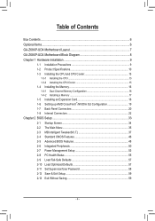
Table of Contents Box Contents...6 Optional Items...6 GA-Z68XP-UD4 Motherboard Layout 7 GA-Z68XP-UD4 Motherboard Block Diagram 8 Chapter 1 Hardware Installation 9 1-1 Installation Precautions 9 1-2 Product Specifications 10 1-3 Installing the CPU and CPU Cooler 13 1-3-1 Installing the CPU 13 1-3-2 Installing the CPU Cooler ...
Table of Contents Box Contents...6 Optional Items...6 GA-Z68XP-UD4 Motherboard Layout 7 GA-Z68XP-UD4 Motherboard Block Diagram 8 Chapter 1 Hardware Installation 9 1-1 Installation Precautions 9 1-2 Product Specifications 10 1-3 Installing the CPU and CPU Cooler 13 1-3-1 Installing the CPU 13 1-3-2 Installing the CPU Cooler ...
User Manual
Page 6
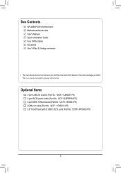
Box Contents GA-Z68XP-UD4 motherboard Motherboard driver disk User's Manual Quick Installation Guide Four SATA cables I/O Shield One 2-Way SLI bridge connector • The box contents above are subject to change ...
Box Contents GA-Z68XP-UD4 motherboard Motherboard driver disk User's Manual Quick Installation Guide Four SATA cables I/O Shield One 2-Way SLI bridge connector • The box contents above are subject to change ...
User Manual
Page 7
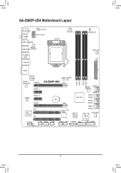
GA-Z68XP-UD4 Motherboard Layout KB_MS_USB R_SPDIF SYS_FAN1 ATX_12V_2X4 USB_1394_ESATA Marvell USB_ESATA 88SE9172 R_USB30 HDMI USB_LAN LGA1155 CPU_FAN PHASE LED PWR_FAN ATX AUDIO Etron EJ168 Realtek RTL8111E/F PCIEX16 PCIEX1_1 CODEC PCIEX1_2 PCIEX8 PCI1 VIA VT6308 PCI2 B_BIOS M_BIOS GA-Z68XP-UD4 DDR3_4 DDR3_2 DDR3_3 DDR3_1 Marvell GSATA3_7 88SE9172 GSATA3_6 SATA3_1 Intel® Z68 SATA3_0 BAT SATA2_3 SATA2_2 PCIe to PCI Bridge Etron EJ168 SATA2_5 SATA2_4 iTE IT8728 SYS_FAN2 F_AUDIO CLR_CMOS F_1394 COMA F_USB3 F_USB2 F_USB1 F_USB30 TPM F_PANEL SPDIF_O - 7 -
GA-Z68XP-UD4 Motherboard Layout KB_MS_USB R_SPDIF SYS_FAN1 ATX_12V_2X4 USB_1394_ESATA Marvell USB_ESATA 88SE9172 R_USB30 HDMI USB_LAN LGA1155 CPU_FAN PHASE LED PWR_FAN ATX AUDIO Etron EJ168 Realtek RTL8111E/F PCIEX16 PCIEX1_1 CODEC PCIEX1_2 PCIEX8 PCI1 VIA VT6308 PCI2 B_BIOS M_BIOS GA-Z68XP-UD4 DDR3_4 DDR3_2 DDR3_3 DDR3_1 Marvell GSATA3_7 88SE9172 GSATA3_6 SATA3_1 Intel® Z68 SATA3_0 BAT SATA2_3 SATA2_2 PCIe to PCI Bridge Etron EJ168 SATA2_5 SATA2_4 iTE IT8728 SYS_FAN2 F_AUDIO CLR_CMOS F_1394 COMA F_USB3 F_USB2 F_USB1 F_USB30 TPM F_PANEL SPDIF_O - 7 -
User Manual
Page 8
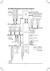
GA-Z68XP-UD4 Motherboard Block Diagram PCIe CLK (100 MHz) 1 PCI Express x16 or 2 PCI Express x8 LGA1155 CPU CPU CLK+/- (100 MHz) DDR3 2133/1866/1600/1333/1066 ...
GA-Z68XP-UD4 Motherboard Block Diagram PCIe CLK (100 MHz) 1 PCI Express x16 or 2 PCI Express x8 LGA1155 CPU CPU CLK+/- (100 MHz) DDR3 2133/1866/1600/1333/1066 ...

User Manual
Page 9
...use of the product, please consult a certified computer technician. - 9 - Hardware Installation Chapter 1 Hardware Installation 1-1 Installation Precautions The motherboard contains numerous delicate electronic circuits and components which can lead to damage to system components as well as physical harm to the user....supply has been turned off. •• Before turning on the computer power during the installation process can become damaged as a motherboard, CPU or memory. If you are uncertain about any metal leads or connectors. •• It is suitable for warranty ...
...use of the product, please consult a certified computer technician. - 9 - Hardware Installation Chapter 1 Hardware Installation 1-1 Installation Precautions The motherboard contains numerous delicate electronic circuits and components which can lead to damage to system components as well as physical harm to the user....supply has been turned off. •• Before turning on the computer power during the installation process can become damaged as a motherboard, CPU or memory. If you are uncertain about any metal leads or connectors. •• It is suitable for warranty ...
User Manual
Page 12
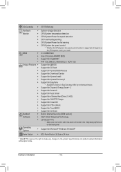
...Center ŠŠ Support for Xpress Install ŠŠ Support for Xpress Recovery2 ŠŠ Support for EasyTune * Available functions in EasyTune may differ by motherboard model. ŠŠ Support for Dynamic Energy Saver™ 2 ŠŠ Support for Smart 6™ ŠŠ Support for Auto Green Š... for TouchBIOS ŠŠ Support for Microsoft® Windows 7/Vista/XP Form Factor ŠŠ ATX Form Factor; 30.5cm x 24.4cm * GIGABYTE reserves the right to make any changes to the integrated graphics port on the CPU/system cooler you install.
...Center ŠŠ Support for Xpress Install ŠŠ Support for Xpress Recovery2 ŠŠ Support for EasyTune * Available functions in EasyTune may differ by motherboard model. ŠŠ Support for Dynamic Energy Saver™ 2 ŠŠ Support for Smart 6™ ŠŠ Support for Auto Green Š... for TouchBIOS ŠŠ Support for Microsoft® Windows 7/Vista/XP Form Factor ŠŠ ATX Form Factor; 30.5cm x 24.4cm * GIGABYTE reserves the right to make any changes to the integrated graphics port on the CPU/system cooler you install.
User Manual
Page 13
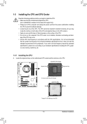
...for the latest CPU support list.) •• Always turn on the computer if the CPU cooler is not recommended that the motherboard supports the CPU. (Go to GIGABYTE's website for the peripherals. If you wish to set beyond the standard specifications, please do so according to your hardware specifications ...incorrectly. (Or you may occur. •• Set the CPU host frequency in accordance with the CPU specifications. Locate the alignment keys on the motherboard CPU socket and the notches on the CPU - 13 - age of the CPU may locate the notches on both sides of the CPU and ...
...for the latest CPU support list.) •• Always turn on the computer if the CPU cooler is not recommended that the motherboard supports the CPU. (Go to GIGABYTE's website for the peripherals. If you wish to set beyond the standard specifications, please do so according to your hardware specifications ...incorrectly. (Or you may occur. •• Set the CPU host frequency in accordance with the CPU specifications. Locate the alignment keys on the motherboard CPU socket and the notches on the CPU - 13 - age of the CPU may locate the notches on both sides of the CPU and ...

User Manual
Page 14
.... When replacing the load plate, make sure to hold the socket lever and use your finger. Step 5: Push the CPU socket lever back into the motherboard CPU socket. Follow the steps below to the "REMOVE" mark) and then remove the cover. (DO NOT touch socket contacts. To protect the CPU socket...
.... When replacing the load plate, make sure to hold the socket lever and use your finger. Step 5: Push the CPU socket lever back into the motherboard CPU socket. Follow the steps below to the "REMOVE" mark) and then remove the cover. (DO NOT touch socket contacts. To protect the CPU socket...
User Manual
Page 15
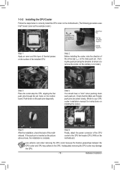
... joined closely. (Refer to install.) Step 3: Place the cooler atop the CPU, aligning the four push pins through the pin holes on the motherboard. Step 2: Before installing the cooler, note the direction of the arrow sign on the male push pin. (Turning the push pin along the ...contrary, is to your CPU cooler installation manual for instructions on installing the cooler.) Step 5: After the installation, check the back of the motherboard. Push down each push pin. Hardware Installation Use extreme care when removing the CPU cooler because the thermal grease/tape between the CPU cooler and...
... joined closely. (Refer to install.) Step 3: Place the cooler atop the CPU, aligning the four push pins through the pin holes on the motherboard. Step 2: Before installing the cooler, note the direction of the arrow sign on the male push pin. (Turning the push pin along the ...contrary, is to your CPU cooler installation manual for instructions on installing the cooler.) Step 5: After the installation, check the back of the motherboard. Push down each push pin. Hardware Installation Use extreme care when removing the CPU cooler because the thermal grease/tape between the CPU cooler and...

User Manual
Page 16
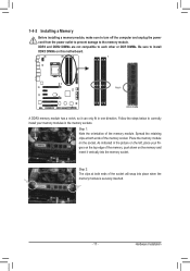
... the original memory bandwidth. After the memory is recommended that you install them in only one DDR3 memory module is recommended that the motherboard supports the memory. Hardware Installation - 16 - Enabling Dual Channel memory mode will automatically detect the specifications and capacity of the memory....Channel mode with two memory modules, we recommend that memory of the same capacity, brand, speed, and chips be used . (Go to GIGABYTE's website for the latest supported memory speeds and memory modules.) •• Always turn off the computer and unplug the power cord from...
... the original memory bandwidth. After the memory is recommended that you install them in only one DDR3 memory module is recommended that the motherboard supports the memory. Hardware Installation - 16 - Enabling Dual Channel memory mode will automatically detect the specifications and capacity of the memory....Channel mode with two memory modules, we recommend that memory of the same capacity, brand, speed, and chips be used . (Go to GIGABYTE's website for the latest supported memory speeds and memory modules.) •• Always turn off the computer and unplug the power cord from...
User Manual
Page 17
... the power outlet to prevent damage to correctly install your fingers on the top edge of the memory module. Place the memory module on this motherboard. As indicated in the picture on the left, place your memory modules in the memory sockets. Follow the steps below to the memory module. Step...
... the power outlet to prevent damage to correctly install your fingers on the top edge of the memory module. Place the memory module on this motherboard. As indicated in the picture on the left, place your memory modules in the memory sockets. Follow the steps below to the memory module. Step...
User Manual
Page 18
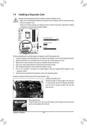
... Installation - 18 - Carefully read the manual that supports your card. If necessary, go to BIOS Setup to install an expansion card: • Make sure the motherboard supports the expansion card. PCI Express x16 Slot PCI Express x1 Slot PCI Slot Follow the steps below to prevent hardware damage.
... Installation - 18 - Carefully read the manual that supports your card. If necessary, go to BIOS Setup to install an expansion card: • Make sure the motherboard supports the expansion card. PCI Express x16 Slot PCI Express x1 Slot PCI Slot Follow the steps below to prevent hardware damage.

User Manual
Page 19
C. C-2. A CrossFireX/SLI-supported motherboard with your graphics cards for more information about enabling CrossFireX/SLI technology. - 19 - Step 3: Plug the display cable into the graphics card on the PCI ...
C. C-2. A CrossFireX/SLI-supported motherboard with your graphics cards for more information about enabling CrossFireX/SLI technology. - 19 - Step 3: Plug the display cable into the graphics card on the PCI ...

User Manual
Page 20
... keyboard. vell 88SE9172 chip supports RAID function. You can use this port for an IEEE 1394a device. Do not rock it straight out from the motherboard. •• When removing the cable, pull it side to side to Chapter 5, "Configuring SATA Hard Drive(s)," for USB devices such as a USB keyboard/mouse...
... keyboard. vell 88SE9172 chip supports RAID function. You can use this port for an IEEE 1394a device. Do not rock it straight out from the motherboard. •• When removing the cable, pull it side to side to Chapter 5, "Configuring SATA Hard Drive(s)," for USB devices such as a USB keyboard/mouse...

User Manual
Page 22
... sure your devices are compliant with the connectors you wish to connect. •• Before installing the devices, be sure to the connector on the motherboard.
... sure your devices are compliant with the connectors you wish to connect. •• Before installing the devices, be sure to the connector on the motherboard.

User Manual
Page 23
Connect the power supply cable to the CPU. To meet expansion requirements, it is turned off and all the components on the motherboard. Before connecting the power connector, first make sure the power supply is recommended that a power supply that does not provide the required power, the result ...
Connect the power supply cable to the CPU. To meet expansion requirements, it is turned off and all the components on the motherboard. Before connecting the power connector, first make sure the power supply is recommended that a power supply that does not provide the required power, the result ...


