
Manual
Page 1
...the Smart Response Technology. 1. Enabling RAID mode in BIOS Setup 3. The actual BIOS Setup menu options you will see shall depend on your motherboard. Installing the operating system and drivers to RAID(XHD). If you use an SSD larger than 64 GB, the space beyond 64 GB can...Technology utility to enable the Intel Smart Response Technology • The Intel Smart Response Technology requires a computer system with an Intel Z68 Chipset-based motherboard and an Intel Core series CPU. • The operating system must be used for your computer and press to enable the Intel® ...
...the Smart Response Technology. 1. Enabling RAID mode in BIOS Setup 3. The actual BIOS Setup menu options you will see shall depend on your motherboard. Installing the operating system and drivers to RAID(XHD). If you use an SSD larger than 64 GB, the space beyond 64 GB can...Technology utility to enable the Intel Smart Response Technology • The Intel Smart Response Technology requires a computer system with an Intel Z68 Chipset-based motherboard and an Intel Core series CPU. • The operating system must be used for your computer and press to enable the Intel® ...

Manual
Page 2
Make sure the Intel Rapid Storage Technology driver version is complete, use the "Xpress Install" function of the motherboard driver disk to open the Intel Rapid Storage Technology utility. - 2 - Launching the Intel Rapid Storage Technology utility to enable the Intel Smart Response Technology: ....5 or above and restarting your system, find the IRST icon in the notification area and double-click it to install all motherboard drivers, including the Intel Rapid Storage Technology driver. Installing the operating system and drivers to the SATA disk: After setting the BIOS, you can...
Make sure the Intel Rapid Storage Technology driver version is complete, use the "Xpress Install" function of the motherboard driver disk to open the Intel Rapid Storage Technology utility. - 2 - Launching the Intel Rapid Storage Technology utility to enable the Intel Smart Response Technology: ....5 or above and restarting your system, find the IRST icon in the notification area and double-click it to install all motherboard drivers, including the Intel Rapid Storage Technology driver. Installing the operating system and drivers to the SATA disk: After setting the BIOS, you can...

Manual
Page 2
Motherboard GA-Z68X-UD3-B3 Apr. 28, 2011 Motherboard GA-Z68X-UD3-B3 Apr. 28, 2011
Motherboard GA-Z68X-UD3-B3 Apr. 28, 2011 Motherboard GA-Z68X-UD3-B3 Apr. 28, 2011

Manual
Page 3
...may be reproduced, copied, translated, transmitted, or published in this product, GIGABYTE provides the following types of documentations: For quick set-up of the motherboard is 1.0. Documentation Classifications In order to their respective owners. For product-related... at: http://www.gigabyte.com Identifying Your Motherboard Revision The revision number on your motherboard revision before updating motherboard BIOS, drivers, or when looking for technical information. Check your motherboard looks like this manual is the property of GIGABYTE. Example: Copyright &#...
...may be reproduced, copied, translated, transmitted, or published in this product, GIGABYTE provides the following types of documentations: For quick set-up of the motherboard is 1.0. Documentation Classifications In order to their respective owners. For product-related... at: http://www.gigabyte.com Identifying Your Motherboard Revision The revision number on your motherboard revision before updating motherboard BIOS, drivers, or when looking for technical information. Check your motherboard looks like this manual is the property of GIGABYTE. Example: Copyright &#...
Manual
Page 4
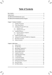
Table of Contents Box Contents...6 Optional Items...6 GA-Z68X-UD3-B3 Motherboard Layout 7 GA-Z68X-UD3-B3 Motherboard Block Diagram 8 Chapter 1 Hardware Installation 9 1-1 Installation Precautions 9 1-2 Product Specifications 10 1-3 Installing the CPU and CPU Cooler 13 1-3-1 Installing the CPU 13 1-3-2 Installing the CPU Cooler ...
Table of Contents Box Contents...6 Optional Items...6 GA-Z68X-UD3-B3 Motherboard Layout 7 GA-Z68X-UD3-B3 Motherboard Block Diagram 8 Chapter 1 Hardware Installation 9 1-1 Installation Precautions 9 1-2 Product Specifications 10 1-3 Installing the CPU and CPU Cooler 13 1-3-1 Installing the CPU 13 1-3-2 Installing the CPU Cooler ...
Manual
Page 6
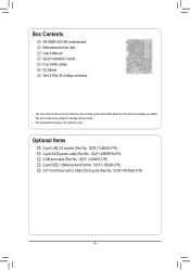
The box contents are for reference only. Box Contents GA-Z68X-UD3-B3 motherboard Motherboard driver disk User's Manual Quick Installation Guide Four SATA cables I/O Shield One 2-Way SLI bridge connector • The box contents above are subject to change without notice. • The motherboard image is for reference only and the actual items shall depend on the...
The box contents are for reference only. Box Contents GA-Z68X-UD3-B3 motherboard Motherboard driver disk User's Manual Quick Installation Guide Four SATA cables I/O Shield One 2-Way SLI bridge connector • The box contents above are subject to change without notice. • The motherboard image is for reference only and the actual items shall depend on the...

Manual
Page 7
GA-Z68X-UD3-B3 Motherboard Layout KB_MS_USB R_SPDIF USB_1394 SYS_FAN1 ATX_12V_2X4 LGA1155 CPU_FAN PHASE LED R_USB R_USB30 USB_LAN AUDIO Etron EJ168 PWR_FAN ATX PCIEX1_1 B_BIOS Realtek RTL8111E CODEC VIA VT6308 PCIEX16 PCIEX1_2 PCIEX1_3 PCIEX8 PCI1 PCI2 DDR3_4 DDR3_2 DDR3_3 DDR3_1 GA-Z68X-UD3-B3 M_BIOS Marvell GSATA3_7 88SE9172 GSATA3_6 SATA3_1 Intel® Z68 SATA3_0 BAT SATA2_3 SATA2_2 SATA2_5 SATA2_4 PCIe to PCI Bridge Etron EJ168 iTE IT8728 SYS_FAN2 F_AUDIO CLR_CMOS F_1394 COMA F_USB3 F_USB2 F_USB1 F_USB30 TPM F_PANEL SPDIF_O - 7 -
GA-Z68X-UD3-B3 Motherboard Layout KB_MS_USB R_SPDIF USB_1394 SYS_FAN1 ATX_12V_2X4 LGA1155 CPU_FAN PHASE LED R_USB R_USB30 USB_LAN AUDIO Etron EJ168 PWR_FAN ATX PCIEX1_1 B_BIOS Realtek RTL8111E CODEC VIA VT6308 PCIEX16 PCIEX1_2 PCIEX1_3 PCIEX8 PCI1 PCI2 DDR3_4 DDR3_2 DDR3_3 DDR3_1 GA-Z68X-UD3-B3 M_BIOS Marvell GSATA3_7 88SE9172 GSATA3_6 SATA3_1 Intel® Z68 SATA3_0 BAT SATA2_3 SATA2_2 SATA2_5 SATA2_4 PCIe to PCI Bridge Etron EJ168 iTE IT8728 SYS_FAN2 F_AUDIO CLR_CMOS F_1394 COMA F_USB3 F_USB2 F_USB1 F_USB30 TPM F_PANEL SPDIF_O - 7 -

Manual
Page 8
GA-Z68X-UD3-B3 Motherboard Block Diagram PCIe CLK (100 MHz) 1 PCI Express x16 or 2 PCI Express x8 LGA1155 CPU CPU CLK+/- (100 MHz) DDR3 2133/1866/1600/1333/1066 ...
GA-Z68X-UD3-B3 Motherboard Block Diagram PCIe CLK (100 MHz) 1 PCI Express x16 or 2 PCI Express x8 LGA1155 CPU CPU CLK+/- (100 MHz) DDR3 2133/1866/1600/1333/1066 ...

Manual
Page 9
...best to wear an electrostatic discharge (ESD) wrist strap when handling electronic com- Chapter 1 Hardware Installation 1-1 Installation Precautions The motherboard contains numerous delicate electronic circuits and components which can lead to damage to system components as well as physical harm to the user...ESD wrist strap, keep your hands dry and first touch a metal object to eliminate static electricity. •• Prior to installing the motherboard, please have a problem related to the use of the product, please consult a certified computer technician. - 9 - These stickers are ...
...best to wear an electrostatic discharge (ESD) wrist strap when handling electronic com- Chapter 1 Hardware Installation 1-1 Installation Precautions The motherboard contains numerous delicate electronic circuits and components which can lead to damage to system components as well as physical harm to the user...ESD wrist strap, keep your hands dry and first touch a metal object to eliminate static electricity. •• Prior to installing the motherboard, please have a problem related to the use of the product, please consult a certified computer technician. - 9 - These stickers are ...

Manual
Page 12
...138; Support for Xpress Install ŠŠ Support for Xpress Recovery2 ŠŠ Support for EasyTune * Available functions in EasyTune may differ by motherboard model. ŠŠ Support for Dynamic Energy Saver™ 2 ŠŠ Support for Smart 6™ ŠŠ Support for Auto ...138;Š Support for Microsoft® Windows 7/Vista/XP Form Factor ŠŠ ATX Form Factor; 30.5cm x 24.4cm * GIGABYTE reserves the right to make any changes to the product specifications and product-related information without prior notice. Hardware ŠŠ System voltage ...
...138; Support for Xpress Install ŠŠ Support for Xpress Recovery2 ŠŠ Support for EasyTune * Available functions in EasyTune may differ by motherboard model. ŠŠ Support for Dynamic Energy Saver™ 2 ŠŠ Support for Smart 6™ ŠŠ Support for Auto ...138;Š Support for Microsoft® Windows 7/Vista/XP Form Factor ŠŠ ATX Form Factor; 30.5cm x 24.4cm * GIGABYTE reserves the right to make any changes to the product specifications and product-related information without prior notice. Hardware ŠŠ System voltage ...

Manual
Page 13
...; Locate the pin one of the CPU Socket LGA1155 CPU Notch Notch Triangle Pin One Marking on the CPU. Locate the alignment keys on the motherboard CPU socket and the notches on the CPU - 13 - age of the CPU. •• Do not turn off the computer and unplug the...requirements for the latest CPU support list.) •• Always turn on the computer if the CPU cooler is not recommended that the motherboard supports the CPU. (Go to GIGABYTE's website for the peripherals. 1-3 Installing the CPU and CPU Cooler Read the following guidelines before you begin to install the CPU: &#...
...; Locate the pin one of the CPU Socket LGA1155 CPU Notch Notch Triangle Pin One Marking on the CPU. Locate the alignment keys on the motherboard CPU socket and the notches on the CPU - 13 - age of the CPU. •• Do not turn off the computer and unplug the...requirements for the latest CPU support list.) •• Always turn on the computer if the CPU cooler is not recommended that the motherboard supports the CPU. (Go to GIGABYTE's website for the peripherals. 1-3 Installing the CPU and CPU Cooler Read the following guidelines before you begin to install the CPU: &#...

Manual
Page 14
... into its locked position. Hold your index finger down and away from the power outlet to prevent damage to correctly install the CPU into the motherboard CPU socket. Hardware Installation - 14 - B.
... into its locked position. Hold your index finger down and away from the power outlet to prevent damage to correctly install the CPU into the motherboard CPU socket. Hardware Installation - 14 - B.

Manual
Page 15
...the thermal grease/tape between the CPU cooler and CPU may damage the CPU. - 15 - Step 6: Finally, attach the power connector of the motherboard. Step 4: You should hear a "click" when pushing down on the push pins diagonally. 1-3-2 Installing the CPU Cooler Follow the steps below ...to correctly install the CPU cooler on the motherboard. (The following procedure uses Intel® boxed cooler as the picture above shows, the installation is to install.) Step 3: Place the cooler...
...the thermal grease/tape between the CPU cooler and CPU may damage the CPU. - 15 - Step 6: Finally, attach the power connector of the motherboard. Step 4: You should hear a "click" when pushing down on the push pins diagonally. 1-3-2 Installing the CPU Cooler Follow the steps below ...to correctly install the CPU cooler on the motherboard. (The following procedure uses Intel® boxed cooler as the picture above shows, the installation is to install.) Step 3: Place the cooler...

Manual
Page 16
...four DDR3 memory sockets are unable to insert the memory, switch the direction. 1-4-1 Dual Channel Memory Configuration This motherboard provides four DDR3 memory sockets and supports Dual Channel Technology. If you are divided into two channels and each... Modules DDR3_4 - Dual Channel mode cannot be enabled if only one direction. It is recommended that the motherboard supports the memory. When enabling Dual Channel mode with two memory modules, we recommend that memory of the...the same capacity, brand, speed, and chips be used . (Go to GIGABYTE's website for optimum performance.
...four DDR3 memory sockets are unable to insert the memory, switch the direction. 1-4-1 Dual Channel Memory Configuration This motherboard provides four DDR3 memory sockets and supports Dual Channel Technology. If you are divided into two channels and each... Modules DDR3_4 - Dual Channel mode cannot be enabled if only one direction. It is recommended that the motherboard supports the memory. When enabling Dual Channel mode with two memory modules, we recommend that memory of the...the same capacity, brand, speed, and chips be used . (Go to GIGABYTE's website for optimum performance.

Manual
Page 17
... DDR DIMMs. Be sure to install DDR3 DIMMs on the socket. Step 1: Note the orientation of the memory module. Place the memory module on this motherboard. Notch DDR3 DIMM A DDR3 memory module has a notch, so it vertically into place when the memory module is securely inserted. - 17 - As indicated in the...
... DDR DIMMs. Be sure to install DDR3 DIMMs on the socket. Step 1: Note the orientation of the memory module. Place the memory module on this motherboard. Notch DDR3 DIMM A DDR3 memory module has a notch, so it vertically into place when the memory module is securely inserted. - 17 - As indicated in the...

Manual
Page 18
... the card and then pull the card straight up from the power outlet before you begin to install an expansion card: • Make sure the motherboard supports the expansion card.
... the card and then pull the card straight up from the power outlet before you begin to install an expansion card: • Make sure the motherboard supports the expansion card.

Manual
Page 19
... the CrossFireX/SLI gold edge connectors on the PCI Express x16 slots. 1-6 Setting up ATI CrossFireX™/NVIDIA SLI Configuration A. System Requirements - A CrossFireX/SLI-supported motherboard with your graphics cards for enabling CrossFireX/SLI technology may be needed or not depending on the PCIEX16 slot. A power supply with sufficient power is...
... the CrossFireX/SLI gold edge connectors on the PCI Express x16 slots. 1-6 Setting up ATI CrossFireX™/NVIDIA SLI Configuration A. System Requirements - A CrossFireX/SLI-supported motherboard with your graphics cards for enabling CrossFireX/SLI technology may be needed or not depending on the PCIEX16 slot. A power supply with sufficient power is...

Manual
Page 20
Optical S/PDIF Out Connector This connector provides digital audio out to an external audio system that your device and then remove it from the motherboard. •• When removing the cable, pull it side to side to prevent an electrical short inside the cable connector. Hardware Installation - 20 - Use this ...
Optical S/PDIF Out Connector This connector provides digital audio out to an external audio system that your device and then remove it from the motherboard. •• When removing the cable, pull it side to side to prevent an electrical short inside the cable connector. Hardware Installation - 20 - Use this ...

Manual
Page 22
... sure your devices are compliant with the connectors you wish to connect. •• Before installing the devices, be sure to the connector on the motherboard. Unplug the power cord from the power outlet to prevent damage to the devices. •• After installing the device and before connecting external devices...
... sure your devices are compliant with the connectors you wish to connect. •• Before installing the devices, be sure to the connector on the motherboard. Unplug the power cord from the power outlet to prevent damage to the devices. •• After installing the device and before connecting external devices...

Manual
Page 23
... is used that can withstand high power consumption be used (500W or greater). If a power supply is turned off and all the components on the motherboard. 1/2) ATX_12V_2X4/ATX (2x2 12V Power Connector and 2x12 Main Power Connector) With the use of the power connector, the power supply can supply enough stable...
... is used that can withstand high power consumption be used (500W or greater). If a power supply is turned off and all the components on the motherboard. 1/2) ATX_12V_2X4/ATX (2x2 12V Power Connector and 2x12 Main Power Connector) With the use of the power connector, the power supply can supply enough stable...


