
Manual
Page 1
...your data. 2. If you back up the hard disk before configuring the Smart Response Technology, all original data on your motherboard. Set PCH SATA Control Mode under the Integrated Peripherals menu to enable the Intel® Smart Response Technology: 1. The maximum cache memory...utility to enable the Intel Smart Response Technology • The Intel Smart Response Technology requires a computer system with an Intel Z68 Chipset-based motherboard and an Intel Core series CPU. • The operating system must be lost once you enable RAID mode. Installing a conventional SATA ...
...your data. 2. If you back up the hard disk before configuring the Smart Response Technology, all original data on your motherboard. Set PCH SATA Control Mode under the Integrated Peripherals menu to enable the Intel® Smart Response Technology: 1. The maximum cache memory...utility to enable the Intel Smart Response Technology • The Intel Smart Response Technology requires a computer system with an Intel Z68 Chipset-based motherboard and an Intel Core series CPU. • The operating system must be lost once you enable RAID mode. Installing a conventional SATA ...

Manual
Page 2
... the steps above . 4. English 3. Make sure the Intel Rapid Storage Technology driver version is complete, use the "Xpress Install" function of the motherboard driver disk to open the Intel Rapid Storage Technology utility. - 2 - After the installation is 10.5 or above and restarting your system, fi...;nd the IRST icon in the notification area and double-click it to install all motherboard drivers, including the Intel Rapid Storage Technology driver. Installing the operating system and drivers to the SATA disk: After setting the BIOS...
... the steps above . 4. English 3. Make sure the Intel Rapid Storage Technology driver version is complete, use the "Xpress Install" function of the motherboard driver disk to open the Intel Rapid Storage Technology utility. - 2 - After the installation is 10.5 or above and restarting your system, fi...;nd the IRST icon in the notification area and double-click it to install all motherboard drivers, including the Intel Rapid Storage Technology driver. Installing the operating system and drivers to the SATA disk: After setting the BIOS...
Manual
Page 3
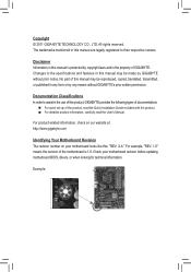
...and is 1.0. Disclaimer Information in this manual is protected by GIGABYTE without GIGABYTE's prior written permission. All rights reserved. For example, "REV: 1.0" means the revision of this : "REV: X.X." Check your motherboard looks like this manual may be reproduced, copied, translated, ...check on our website at: http://www.gigabyte.com Identifying Your Motherboard Revision The revision number on your motherboard revision before updating motherboard BIOS, drivers, or when looking for technical information. No part of the motherboard is the property of the product, read...
...and is 1.0. Disclaimer Information in this manual is protected by GIGABYTE without GIGABYTE's prior written permission. All rights reserved. For example, "REV: 1.0" means the revision of this : "REV: X.X." Check your motherboard looks like this manual may be reproduced, copied, translated, ...check on our website at: http://www.gigabyte.com Identifying Your Motherboard Revision The revision number on your motherboard revision before updating motherboard BIOS, drivers, or when looking for technical information. No part of the motherboard is the property of the product, read...
Manual
Page 4
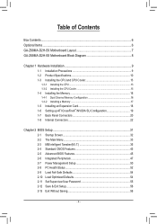
Table of Contents Box Contents...6 Optional Items...6 GA-Z68MA-D2H-B3 Motherboard Layout 7 GA-Z68MA-D2H-B3 Motherboard Block Diagram 8 Chapter 1 Hardware Installation 9 1-1 Installation Precautions 9 1-2 Product Specifications 10 1-3 Installing the CPU and CPU Cooler 13 1-3-1 Installing the CPU 13 1-3-2 Installing the CPU Cooler ...
Table of Contents Box Contents...6 Optional Items...6 GA-Z68MA-D2H-B3 Motherboard Layout 7 GA-Z68MA-D2H-B3 Motherboard Block Diagram 8 Chapter 1 Hardware Installation 9 1-1 Installation Precautions 9 1-2 Product Specifications 10 1-3 Installing the CPU and CPU Cooler 13 1-3-1 Installing the CPU 13 1-3-2 Installing the CPU Cooler ...
Manual
Page 6
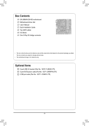
Box Contents GA-Z68MA-D2H-B3 motherboard Motherboard driver disk User's Manual Quick Installation Guide Two SATA cables I/O Shield One 2-Way SLI bridge connector • The box contents above are subject to change without notice. • The motherboard image is for reference only and the actual items shall depend on the product package you obtain. The box contents are for reference only. Optional Items 2-port USB 2.0 bracket (Part No. 12CR1-1UB030-5*R) 2-port SATA power cable (Part No. 12CF1-2SERPW-0*R) COM port cable (Part No. 12CF1-1CM001-3*R) - 6 -
Box Contents GA-Z68MA-D2H-B3 motherboard Motherboard driver disk User's Manual Quick Installation Guide Two SATA cables I/O Shield One 2-Way SLI bridge connector • The box contents above are subject to change without notice. • The motherboard image is for reference only and the actual items shall depend on the product package you obtain. The box contents are for reference only. Optional Items 2-port USB 2.0 bracket (Part No. 12CR1-1UB030-5*R) 2-port SATA power cable (Part No. 12CF1-2SERPW-0*R) COM port cable (Part No. 12CF1-1CM001-3*R) - 6 -
Manual
Page 7
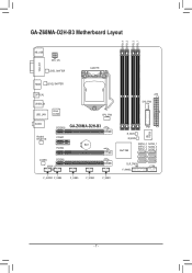
GA-Z68MA-D2H-B3 Motherboard Layout DDR3_4 DDR3_2 DDR3_3 DDR3_1 KB_USB ATX_12V VGA_DVI LEVEL SHIFTER LGA1155 HDMI LEVEL SHIFTER OPTICAL USB30_20 USB_LAN Etron EJ168 CPU_FAN AUDIO PCIEX16 GA-Z68MA-D2H-B3 Realtek RTL8111E PCIEX1 BAT PCIEX4 CODEC PCIEX8 SPDIF_O F_AUDIO F_USB4 F_USB3 F_USB2 F_USB1 ATX SYS_FAN TPM iTE IT8728 B_BIOS M_BIOS Intel® Z68 SATA3_0 SATA3_1 SATA2_2 SATA2_3 SATA2_4 SATA2_5 CLR_CMOS COM F_PANEL - 7 -
GA-Z68MA-D2H-B3 Motherboard Layout DDR3_4 DDR3_2 DDR3_3 DDR3_1 KB_USB ATX_12V VGA_DVI LEVEL SHIFTER LGA1155 HDMI LEVEL SHIFTER OPTICAL USB30_20 USB_LAN Etron EJ168 CPU_FAN AUDIO PCIEX16 GA-Z68MA-D2H-B3 Realtek RTL8111E PCIEX1 BAT PCIEX4 CODEC PCIEX8 SPDIF_O F_AUDIO F_USB4 F_USB3 F_USB2 F_USB1 ATX SYS_FAN TPM iTE IT8728 B_BIOS M_BIOS Intel® Z68 SATA3_0 SATA3_1 SATA2_2 SATA2_3 SATA2_4 SATA2_5 CLR_CMOS COM F_PANEL - 7 -
Manual
Page 8
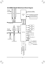
GA-Z68MA-D2H-B3 Motherboard Block Diagram PCIe CLK (100 MHz) CPU CLK+/- (100 MHz) 1 PCI Express x16 or 2 PCI Express x8 LGA1155 CPU DDR3 2133/1866/1600/1333/1066 ...
GA-Z68MA-D2H-B3 Motherboard Block Diagram PCIe CLK (100 MHz) CPU CLK+/- (100 MHz) 1 PCI Express x16 or 2 PCI Express x8 LGA1155 CPU DDR3 2133/1866/1600/1333/1066 ...
Manual
Page 9
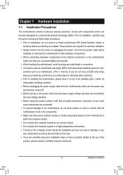
...do not have an ESD wrist strap, keep your dealer. These stickers are connected tightly and securely. •• When handling the motherboard, avoid touching any installation steps or have it on top of an antistatic pad or within an electrostatic shielding container. •• Before...remove the AC power by your hands dry and first touch a metal object to eliminate static electricity. •• Prior to installing the motherboard, please have a problem related to the use of electrostatic discharge (ESD). If you are uncertain about any metal leads or connectors. &#...
...do not have an ESD wrist strap, keep your dealer. These stickers are connected tightly and securely. •• When handling the motherboard, avoid touching any installation steps or have it on top of an antistatic pad or within an electrostatic shielding container. •• Before...remove the AC power by your hands dry and first touch a metal object to eliminate static electricity. •• Prior to installing the motherboard, please have a problem related to the use of electrostatic discharge (ESD). If you are uncertain about any metal leads or connectors. &#...
Manual
Page 12
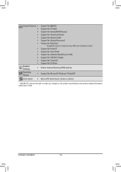
...138; Support for Xpress Install ŠŠ Support for Xpress Recovery2 ŠŠ Support for EasyTune * Available functions in EasyTune may differ by motherboard model. ŠŠ Support for Smart 6™ ŠŠ Support for Auto Green ŠŠ Support for eXtreme Hard Drive (X.H.D) Š...; Support for Microsoft® Windows 7/Vista/XP Form Factor ŠŠ Micro ATX Form Factor; 24.4cm x 24.4cm * GIGABYTE reserves the right to make any changes to the product specifications and product-related information without prior notice. Hardware Installation - 12 -
...138; Support for Xpress Install ŠŠ Support for Xpress Recovery2 ŠŠ Support for EasyTune * Available functions in EasyTune may differ by motherboard model. ŠŠ Support for Smart 6™ ŠŠ Support for Auto Green ŠŠ Support for eXtreme Hard Drive (X.H.D) Š...; Support for Microsoft® Windows 7/Vista/XP Form Factor ŠŠ Micro ATX Form Factor; 24.4cm x 24.4cm * GIGABYTE reserves the right to make any changes to the product specifications and product-related information without prior notice. Hardware Installation - 12 -

Manual
Page 13
...;• Locate the pin one of the CPU. Locate the alignment keys on the motherboard CPU socket and the notches on the computer if the CPU cooler is not recommended that the motherboard supports the CPU. (Go to GIGABYTE's website for the peripherals. Hardware Installation age of the CPU Socket LGA1155 CPU Notch...
...;• Locate the pin one of the CPU. Locate the alignment keys on the motherboard CPU socket and the notches on the computer if the CPU cooler is not recommended that the motherboard supports the CPU. (Go to GIGABYTE's website for the peripherals. Hardware Installation age of the CPU Socket LGA1155 CPU Notch...

Manual
Page 14
Step 2: Remove the CPU socket cover as well. Step 5: Push the CPU socket lever back into the motherboard CPU socket. Then completely lift the CPU socket lever and the metal load plate will be lifted as shown. Align the CPU pin one marking (...
Step 2: Remove the CPU socket cover as well. Step 5: Push the CPU socket lever back into the motherboard CPU socket. Then completely lift the CPU socket lever and the metal load plate will be lifted as shown. Align the CPU pin one marking (...

Manual
Page 15
...Step 1: Apply an even and thin layer of thermal grease on the surface of the CPU cooler to the CPU fan header (CPU_FAN) on the motherboard. Push down each push pin. Step 4: You should hear a "click" when pushing down on the push pins diagonally. 1-3-2 Installing the CPU Cooler... Follow the steps below to correctly install the CPU cooler on the motherboard. (The following procedure uses Intel® boxed cooler as the picture above shows, the installation is to install.) Step 3: Place the cooler atop ...
...Step 1: Apply an even and thin layer of thermal grease on the surface of the CPU cooler to the CPU fan header (CPU_FAN) on the motherboard. Push down each push pin. Step 4: You should hear a "click" when pushing down on the push pins diagonally. 1-3-2 Installing the CPU Cooler... Follow the steps below to correctly install the CPU cooler on the motherboard. (The following procedure uses Intel® boxed cooler as the picture above shows, the installation is to install.) Step 3: Place the cooler atop ...

Manual
Page 16
...them in only one DDR3 memory module is installed. 222 When enabling Dual Channel mode with two memory modules, we recommend that the motherboard supports the memory. 1-4 Installing the Memory Read the following : Channel A: DDR3_2, DDR3_4 Channel B: DDR3_1, DDR3_3 Dual Channel Memory ... Four Modules DDR3_4 - DS/SS (SS=Single-Sided, DS=Double-Sided, "- -"=No Memory) DDR3_4 DDR3_2 DDR3_3 DDR3_1 Due to GIGABYTE's website for optimum performance. Enabling Dual Channel memory mode will automatically detect the specifications and capacity of the same capacity, brand, speed...
...them in only one DDR3 memory module is installed. 222 When enabling Dual Channel mode with two memory modules, we recommend that the motherboard supports the memory. 1-4 Installing the Memory Read the following : Channel A: DDR3_2, DDR3_4 Channel B: DDR3_1, DDR3_3 Dual Channel Memory ... Four Modules DDR3_4 - DS/SS (SS=Single-Sided, DS=Double-Sided, "- -"=No Memory) DDR3_4 DDR3_2 DDR3_3 DDR3_1 Due to GIGABYTE's website for optimum performance. Enabling Dual Channel memory mode will automatically detect the specifications and capacity of the same capacity, brand, speed...

Manual
Page 17
..., make sure to turn off the computer and unplug the power cord from the power outlet to prevent damage to install DDR3 DIMMs on this motherboard.
..., make sure to turn off the computer and unplug the power cord from the power outlet to prevent damage to install DDR3 DIMMs on this motherboard.
Manual
Page 18
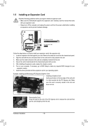
... the PCI Express slot. PCI Express x16 Slot PCI Express x1 Slot Follow the steps below to install an expansion card: • Make sure the motherboard supports the expansion card.
... the PCI Express slot. PCI Express x16 Slot PCI Express x1 Slot Follow the steps below to install an expansion card: • Make sure the motherboard supports the expansion card.
Manual
Page 19
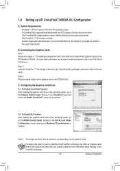
... PCIEX8 slots.) Step 2: Insert the CrossFire (Note)/SLI bridge connector in the operating system, go to the Catalyst Control Center. System Requirements - A CrossFireX/SLI-supported motherboard with your graphics cards for enabling CrossFireX/SLI technology may be needed or not depending on the PCIEX16 slot.
... PCIEX8 slots.) Step 2: Insert the CrossFire (Note)/SLI bridge connector in the operating system, go to the Catalyst Control Center. System Requirements - A CrossFireX/SLI-supported motherboard with your graphics cards for enabling CrossFireX/SLI technology may be needed or not depending on the PCIEX16 slot.
Manual
Page 21
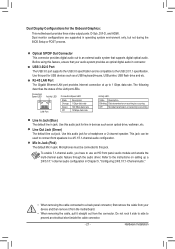
...2/4/5.1/7.1-Channel Audio." •• When removing the cable connected to an external audio system that your device and then remove it from the motherboard. •• When removing the cable, pull it side to side to the USB 2.0/1.1 specification. Microphones must be used to this ...audio jack for the Onboard Graphics: This motherboard provides three video output ports: D-Sub, DVI-D, and HDMI. Dual monitor configurations are supported in operating system environment only, but not ...
...2/4/5.1/7.1-Channel Audio." •• When removing the cable connected to an external audio system that your device and then remove it from the motherboard. •• When removing the cable, pull it side to side to the USB 2.0/1.1 specification. Microphones must be used to this ...audio jack for the Onboard Graphics: This motherboard provides three video output ports: D-Sub, DVI-D, and HDMI. Dual monitor configurations are supported in operating system environment only, but not ...

Manual
Page 22
... sure your devices are compliant with the connectors you wish to connect. •• Before installing the devices, be sure to the connector on the motherboard. Hardware Installation - 22 - Unplug the power cord from the power outlet to prevent damage to the devices. •• After installing the device and before...
... sure your devices are compliant with the connectors you wish to connect. •• Before installing the devices, be sure to the connector on the motherboard. Hardware Installation - 22 - Unplug the power cord from the power outlet to prevent damage to the devices. •• After installing the device and before...

Manual
Page 23
... power connector mainly supplies power to all devices are properly installed. If the 12V power connector is turned off and all the components on the motherboard. Before connecting the power connector, first make sure the power supply is not connected, the computer will not start. The power connector possesses a foolproof design...
... power connector mainly supplies power to all devices are properly installed. If the 12V power connector is turned off and all the components on the motherboard. Before connecting the power connector, first make sure the power supply is not connected, the computer will not start. The power connector possesses a foolproof design...

Manual
Page 24
... handled in the power cord and restart your computer. •• Always turn off . Danger of the battery holder, making them short for one . The motherboard supports CPU fan speed control, which requires the use a metal object like a screwdriver to the CPU or the system may be accurate or may hang... in the CMOS when the computer is the ground wire). Hardware Installation - 24 - Most fan headers possess a foolproof insertion design. 3/4) CPU_FAN/SYS_FAN (Fan Headers) The motherboard has a 4-pin CPU fan header (CPU_FAN), a 4-pin system fan header (SYS_FAN).
... handled in the power cord and restart your computer. •• Always turn off . Danger of the battery holder, making them short for one . The motherboard supports CPU fan speed control, which requires the use a metal object like a screwdriver to the CPU or the system may be accurate or may hang... in the CMOS when the computer is the ground wire). Hardware Installation - 24 - Most fan headers possess a foolproof insertion design. 3/4) CPU_FAN/SYS_FAN (Fan Headers) The motherboard has a 4-pin CPU fan header (CPU_FAN), a 4-pin system fan header (SYS_FAN).


