
Manual
Page 1
...drive is greater than or equal to expand its capacity. For a RAID 0 array that before you run the X.H.D utility, back up all motherboard drivers, including the X.H.D utility. To automatically set up a RAID 0 array: Click Auto to set up a RAID-ready system and configure it... for the Intel SATA controllers. eXtreme Hard Drive (X.H.D) With GIGABYTE eXtreme Hard Drive (X.H.D)(Note 1), users can quickly configure a RAIDready system for complex and time-consuming configurations. The following procedure details the steps...
...drive is greater than or equal to expand its capacity. For a RAID 0 array that before you run the X.H.D utility, back up all motherboard drivers, including the X.H.D utility. To automatically set up a RAID 0 array: Click Auto to set up a RAID-ready system and configure it... for the Intel SATA controllers. eXtreme Hard Drive (X.H.D) With GIGABYTE eXtreme Hard Drive (X.H.D)(Note 1), users can quickly configure a RAIDready system for complex and time-consuming configurations. The following procedure details the steps...

Manual
Page 1
GA-X58A-UD7 LGA1366 socket motherboard for Intel® Core™ i7 processor family User's Manual Rev. 1002 12ME-X58AUD7-1002R
GA-X58A-UD7 LGA1366 socket motherboard for Intel® Core™ i7 processor family User's Manual Rev. 1002 12ME-X58AUD7-1002R
Manual
Page 2
Motherboard GA-X58A-UD7 Nov. 13, 2009 Motherboard GA-X58A-UD7 Nov. 13, 2009
Motherboard GA-X58A-UD7 Nov. 13, 2009 Motherboard GA-X58A-UD7 Nov. 13, 2009

Manual
Page 3
... written permission. For instructions on how to the specifications and features in this manual is protected by copyright laws and is 1.0. Check your motherboard looks like this product, GIGABYTE provides the following types of documentations: For quick set-up of this : "REV: X.X." Changes to use of the product, read the Quick Installation...
... written permission. For instructions on how to the specifications and features in this manual is protected by copyright laws and is 1.0. Check your motherboard looks like this product, GIGABYTE provides the following types of documentations: For quick set-up of this : "REV: X.X." Changes to use of the product, read the Quick Installation...

Manual
Page 4
Table of Contents Box Contents...6 Optional Items...6 GA-X58A-UD7 Motherboard Layout 7 Block Diagram...8 Chapter 1 Hardware Installation 9 1-1 Installation Precautions 9 1-2 Product Specifications 10 1-3 Installing the CPU and CPU Cooler 13 1-3-1 Installing the CPU 13 1-3-2 Installing the CPU ...
Table of Contents Box Contents...6 Optional Items...6 GA-X58A-UD7 Motherboard Layout 7 Block Diagram...8 Chapter 1 Hardware Installation 9 1-1 Installation Precautions 9 1-2 Product Specifications 10 1-3 Installing the CPU and CPU Cooler 13 1-3-1 Installing the CPU 13 1-3-2 Installing the CPU ...

Manual
Page 6
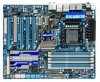
...port SATA power cable (Part No. 12CF1-2SERPW-0*R) S/PDIF In cable (Part No. 12CR1-1SPDIN-0*R) - 6 - The box contents are for reference only. Box Contents GA-X58A-UD7 motherboard Motherboard driver disk User's Manual Quick Installation Guide One IDE cable Four SATA 3Gb/s cables One SATA bracket I/O Shield One Hybrid Silent-Pipe module kit 2-Way... SLI bridge connector 3-Way SLI bridge connector • The box contents above are subject to change without notice. • The motherboard image is for reference only and the actual items shall depend on the product package you obtain.
...port SATA power cable (Part No. 12CF1-2SERPW-0*R) S/PDIF In cable (Part No. 12CR1-1SPDIN-0*R) - 6 - The box contents are for reference only. Box Contents GA-X58A-UD7 motherboard Motherboard driver disk User's Manual Quick Installation Guide One IDE cable Four SATA 3Gb/s cables One SATA bracket I/O Shield One Hybrid Silent-Pipe module kit 2-Way... SLI bridge connector 3-Way SLI bridge connector • The box contents above are subject to change without notice. • The motherboard image is for reference only and the actual items shall depend on the product package you obtain.

Manual
Page 7
...card. LED PHASE LED KB_MS R_SPDIF ATX_12V_2X CMOS_SW USB_1394_ESATA_2 USB_1394_ESATA_1 CPU_FAN CPU Voltage L1/2/3 CPU TEMP L1/2 LGA1366 RST_SW PW_SW GA-X58A-UD7 PWR_FAN USB_LAN ATX USB30_LAN JMicron JMB362 DDR Voltage LED DDR PHASE LED F_AUDIO NB TEMP L1/2 AUDIO NEC PCIEX1_1(Note ...® ICH10R Marvell 9128 SATA2_1 SATA2_0 SATA2_3 SATA2_2 SATA2_5 SATA2_4 GSATA3_7 GSATA3_6 SYS_FAN3 TSB43AB23 GIGABYTE SATA2 Debug LED (Note 2) GSATA2_9 GSATA2_8 SYS_FAN2 F_USB2 IDE F_PANEL FDD F_1394 F_USB1 (Note 1) Due to Chapter 5. - 7 - GA-X58A-UD7 Motherboard Layout FREQ.
...card. LED PHASE LED KB_MS R_SPDIF ATX_12V_2X CMOS_SW USB_1394_ESATA_2 USB_1394_ESATA_1 CPU_FAN CPU Voltage L1/2/3 CPU TEMP L1/2 LGA1366 RST_SW PW_SW GA-X58A-UD7 PWR_FAN USB_LAN ATX USB30_LAN JMicron JMB362 DDR Voltage LED DDR PHASE LED F_AUDIO NB TEMP L1/2 AUDIO NEC PCIEX1_1(Note ...® ICH10R Marvell 9128 SATA2_1 SATA2_0 SATA2_3 SATA2_2 SATA2_5 SATA2_4 GSATA3_7 GSATA3_6 SYS_FAN3 TSB43AB23 GIGABYTE SATA2 Debug LED (Note 2) GSATA2_9 GSATA2_8 SYS_FAN2 F_USB2 IDE F_PANEL FDD F_1394 F_USB1 (Note 1) Due to Chapter 5. - 7 - GA-X58A-UD7 Motherboard Layout FREQ.

Manual
Page 9
...Always remove the AC power by your hands dry and first touch a metal object to eliminate static electricity. • Prior to installing the motherboard, please have a problem related to wear an electrostatic discharge (ESD) wrist strap when handling electronic com- If you are connected tightly and ...securely. • When handling the motherboard, avoid touching any installation steps or have it on top of an antistatic pad or within the computer casing. • Do not...
...Always remove the AC power by your hands dry and first touch a metal object to eliminate static electricity. • Prior to installing the motherboard, please have a problem related to wear an electrostatic discharge (ESD) wrist strap when handling electronic com- If you are connected tightly and ...securely. • When handling the motherboard, avoid touching any installation steps or have it on top of an antistatic pad or within the computer casing. • Do not...

Manual
Page 12
... speed control function is supported will operate at up to install it is recommended that you install. (Note 5) Available functions in EasyTune may differ by motherboard model. if you are installing two PCI Express graphics cards, it in the PCIEX16_1 slot; when PCIEX8_2 is populated with the PCIEX16_1 and PCIEX16_2 slots...
... speed control function is supported will operate at up to install it is recommended that you install. (Note 5) Available functions in EasyTune may differ by motherboard model. if you are installing two PCI Express graphics cards, it in the PCIEX16_1 slot; when PCIEX8_2 is populated with the PCIEX16_1 and PCIEX16_2 slots...
Manual
Page 13
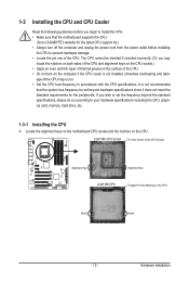
... the computer and unplug the power cord from the power outlet before you begin to install the CPU: • Make sure that the motherboard supports the CPU. (Go to GIGABYTE's website for the latest CPU support list.) • Always turn on the computer if the CPU cooler is not recommended that the... pin one of the CPU Socket Alignment Key Alignment Key LGA1366 CPU Triangle Pin One Marking on the CPU. Locate the alignment keys on the motherboard CPU socket and the notches on the CPU Notch Notch - 13 - The CPU cannot be set the frequency beyond hardware specifications since it does ...
... the computer and unplug the power cord from the power outlet before you begin to install the CPU: • Make sure that the motherboard supports the CPU. (Go to GIGABYTE's website for the latest CPU support list.) • Always turn on the computer if the CPU cooler is not recommended that the... pin one of the CPU Socket Alignment Key Alignment Key LGA1366 CPU Triangle Pin One Marking on the CPU. Locate the alignment keys on the motherboard CPU socket and the notches on the CPU Notch Notch - 13 - The CPU cannot be set the frequency beyond hardware specifications since it does ...
Manual
Page 14
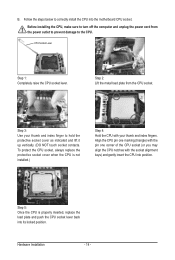
..., always replace the protective socket cover when the CPU is properly inserted, replace the load plate and push the CPU socket lever back into the motherboard CPU socket. Align the CPU pin one marking (triangle) with the pin one corner of the CPU socket (or you may align the CPU notches...
..., always replace the protective socket cover when the CPU is properly inserted, replace the load plate and push the CPU socket lever back into the motherboard CPU socket. Align the CPU pin one marking (triangle) with the pin one corner of the CPU socket (or you may align the CPU notches...

Manual
Page 15
...CPU Cooler Follow the steps below to correctly install the CPU cooler on the motherboard. (The following procedure uses Intel® boxed cooler as the picture above shows...- 15 - Step 6: Finally, attach the power connector of arrow is to remove the cooler, on the motherboard. Hardware Installation Direction of the Arrow Sign on the Male Push Pin Male Push Pin The Top of Female ...Pin Step 2: Before installing the cooler, note the direction of the arrow sign on the surface of the motherboard. Push down each push pin. If the push pin is inserted as the example cooler.) Step 1: Apply...
...CPU Cooler Follow the steps below to correctly install the CPU cooler on the motherboard. (The following procedure uses Intel® boxed cooler as the picture above shows...- 15 - Step 6: Finally, attach the power connector of arrow is to remove the cooler, on the motherboard. Hardware Installation Direction of the Arrow Sign on the Male Push Pin Male Push Pin The Top of Female ...Pin Step 2: Before installing the cooler, note the direction of the arrow sign on the surface of the motherboard. Push down each push pin. If the push pin is inserted as the example cooler.) Step 1: Apply...
Manual
Page 16
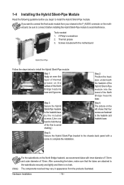
... Silent-Pipe Follow the steps below to complete the installation. (Note) For the waterblocks on the motherboard, be sure to connect it grooves. After connecting the tubes, make sure that four screws are attached to the heatsink and heatsink base. The components ...
... Silent-Pipe Follow the steps below to complete the installation. (Note) For the waterblocks on the motherboard, be sure to connect it grooves. After connecting the tubes, make sure that four screws are attached to the heatsink and heatsink base. The components ...

Manual
Page 17
...Flex Memory Mode will automatically detect the specifications and capacity of the same capacity, brand, speed, and chips be used . (Go to GIGABYTE's website for the latest memory support list.) • Always turn off the computer and unplug the power cord from the power outlet ...DDR3_3 sockets. 3 Channel-1. 3 Channel mode cannot be sure to insert the memory, switch the direction. 1-5-1 Dual/3 Channel Memory Configuration This motherboard provides six DDR3 memory sockets and supports Dual/3 Channel Technology. The six DDR3 memory sockets are unable to install them in only one or ...
...Flex Memory Mode will automatically detect the specifications and capacity of the same capacity, brand, speed, and chips be used . (Go to GIGABYTE's website for the latest memory support list.) • Always turn off the computer and unplug the power cord from the power outlet ...DDR3_3 sockets. 3 Channel-1. 3 Channel mode cannot be sure to insert the memory, switch the direction. 1-5-1 Dual/3 Channel Memory Configuration This motherboard provides six DDR3 memory sockets and supports Dual/3 Channel Technology. The six DDR3 memory sockets are unable to install them in only one or ...

Manual
Page 18
... DDR DIMMs. Be sure to install DDR3 DIMMs on the socket. Follow the steps below to the memory module. Place the memory module on this motherboard. 1-5-2 Installing a Memory Before installing a memory module, make sure to turn off the computer and unplug the power cord from the power outlet to prevent damage...
... DDR DIMMs. Be sure to install DDR3 DIMMs on the socket. Follow the steps below to the memory module. Place the memory module on this motherboard. 1-5-2 Installing a Memory Before installing a memory module, make sure to turn off the computer and unplug the power cord from the power outlet to prevent damage...

Manual
Page 19
... damage. Remove the metal slot cover from the slot. - 19 - If necessary, go to BIOS Setup to install an expansion card: • Make sure the motherboard supports the expansion card. Install the driver provided with a screw. 5. Make sure the metal contacts on your expansion card in the expansion slot. 1. Make sure...
... damage. Remove the metal slot cover from the slot. - 19 - If necessary, go to BIOS Setup to install an expansion card: • Make sure the motherboard supports the expansion card. Install the driver provided with a screw. 5. Make sure the metal contacts on your expansion card in the expansion slot. 1. Make sure...

Manual
Page 20
... came with your graphics cards for the power requirement) B. Browse to the CrossFireX menu and select the Enable CrossFireX™ check box. A CrossFireX/SLI-supported motherboard with sufficient power is enabled. (Note) The bridge connectors may differ by graphics cards. One/two CrossFire (Note)/SLI bridge connectors - Browse to the Set...
... came with your graphics cards for the power requirement) B. Browse to the CrossFireX menu and select the Enable CrossFireX™ check box. A CrossFireX/SLI-supported motherboard with sufficient power is enabled. (Note) The bridge connectors may differ by graphics cards. One/two CrossFire (Note)/SLI bridge connectors - Browse to the Set...
Manual
Page 21
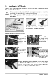
... to install the SATA bracket: Step 1: Locate one SATA power cable. Step 3: Connect the power cable from the bracket to the power connector on your motherboard. Before connecting the SATA signal cable, make sure to turn off your SATA device. SATA Bracket SATA Signal Cable SATA Power Cable External SATA Connector...
... to install the SATA bracket: Step 1: Locate one SATA power cable. Step 3: Connect the power cable from the bracket to the power connector on your motherboard. Before connecting the SATA signal cable, make sure to turn off your SATA device. SATA Bracket SATA Signal Cable SATA Power Cable External SATA Connector...
Manual
Page 22
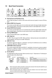
... a coaxial digital audio in connector. Use the port to prevent an electrical short inside the cable connector. Do not rock it straight out from the motherboard. • When removing the cable, pull it side to side to connect an external SATA device or a SATA port multiplier; Optical S/PDIF Out Connector This...
... a coaxial digital audio in connector. Use the port to prevent an electrical short inside the cable connector. Do not rock it straight out from the motherboard. • When removing the cable, pull it side to side to connect an external SATA device or a SATA port multiplier; Optical S/PDIF Out Connector This...

Manual
Page 24
... (red) NB TEMP Off: Below 60oC L1: 61~ 80oC (green) L2: Over 80oC (red) Hardware Installation - 24 - 1-10 Onboard LEDs and Switches Overvoltage LEDs This motherboard contains 4 sets of overvoltage LEDs which level the CPU is overclocked. LED Off: Normal condition F_LED1~F_LED5: Blue Temperature Indicator LEDs The two sets of...
... (red) NB TEMP Off: Below 60oC L1: 61~ 80oC (green) L2: Over 80oC (red) Hardware Installation - 24 - 1-10 Onboard LEDs and Switches Overvoltage LEDs This motherboard contains 4 sets of overvoltage LEDs which level the CPU is overclocked. LED Off: Normal condition F_LED1~F_LED5: Blue Temperature Indicator LEDs The two sets of...


