Manual
Page 1
GA-X38-DS4 LGA775 socket motherboard for Intel® CoreTM processor family/ Intel® Pentium® processor family/Intel® Celeron® processor family User's Manual Rev. 1001 12ME-X38DS4-1001R
GA-X38-DS4 LGA775 socket motherboard for Intel® CoreTM processor family/ Intel® Pentium® processor family/Intel® Celeron® processor family User's Manual Rev. 1001 12ME-X38DS4-1001R

Manual
Page 2
Motherboard GA-X38-DS4 Dec. 7, 2007 Motherboard GA-X38-DS4 Dec. 7, 2007
Motherboard GA-X38-DS4 Dec. 7, 2007 Motherboard GA-X38-DS4 Dec. 7, 2007
Manual
Page 3
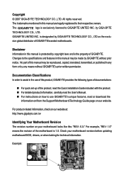
...documentations: „ For quick set-up of this manual are legally registered to GIGABYTE UNITED INC. For product-related information, check on our website at: http://www.gigabyte.com.tw Identifying Your Motherboard Revision The revision number on our website. No part of the product, read...to the specifications and features in any form or by any means without prior notice. For example, "REV: 1.0" means the revision of GIGABYTE branded motherboards. The logo is protected by GIGA-BYTE TECHNOLOGY CO., LTD as the exclu- Copyright © 2007 GIGA-BYTE TECHNOLOGY CO., LTD....
...documentations: „ For quick set-up of this manual are legally registered to GIGABYTE UNITED INC. For product-related information, check on our website at: http://www.gigabyte.com.tw Identifying Your Motherboard Revision The revision number on our website. No part of the product, read...to the specifications and features in any form or by any means without prior notice. For example, "REV: 1.0" means the revision of GIGABYTE branded motherboards. The logo is protected by GIGA-BYTE TECHNOLOGY CO., LTD as the exclu- Copyright © 2007 GIGA-BYTE TECHNOLOGY CO., LTD....
Manual
Page 4
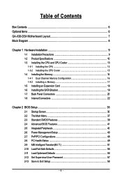
Table of Contents Box Contents ...6 OptionalItems ...6 GA-X38-DS4 Motherboard Layout 7 Block Diagram ...8 Chapter 1 Hardware Installation 9 1-1 Installation Precautions 9 1-2 Product Specifications 10 1-3 Installing the CPU and CPU Cooler 13 1-3-1 Installing the CPU 13 1-3-2 Installing the CPU ...
Table of Contents Box Contents ...6 OptionalItems ...6 GA-X38-DS4 Motherboard Layout 7 Block Diagram ...8 Chapter 1 Hardware Installation 9 1-1 Installation Precautions 9 1-2 Product Specifications 10 1-3 Installing the CPU and CPU Cooler 13 1-3-1 Installing the CPU 13 1-3-2 Installing the CPU ...

Manual
Page 6
... in cable (Part No. 12CR1-1SPDIN-01R) COM port cable (Part No. 12CF1-1CM001-32R) LPT port cable (Part No. 12CF1-1LP001-01R) - 6 - Box Contents GA-X38-DS4 motherboard Motherboard driver disk User's Manual Quick Installation Guide Intel® LGA775 CPU Installation Guide One IDE cable and one floppy disk drive cable Four SATA 3Gb.../s cables One SATA bracket I/O Shield • The box contents above are subject to change without notice. • The motherboard image is for reference only and the actual items shall depend on product package you obtain.
... in cable (Part No. 12CR1-1SPDIN-01R) COM port cable (Part No. 12CF1-1CM001-32R) LPT port cable (Part No. 12CF1-1LP001-01R) - 6 - Box Contents GA-X38-DS4 motherboard Motherboard driver disk User's Manual Quick Installation Guide Intel® LGA775 CPU Installation Guide One IDE cable and one floppy disk drive cable Four SATA 3Gb.../s cables One SATA bracket I/O Shield • The box contents above are subject to change without notice. • The motherboard image is for reference only and the actual items shall depend on product package you obtain.
Manual
Page 7
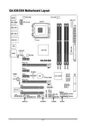
GA-X38-DS4 Motherboard Layout KB_MS RCA_SPDIF USB_1394_1 SYS_FAN1 ATX_12V_2X LGA775 CPU_FAN PCIE_12V ATX USB_1394_2 USB_LAN USB PWR_FAN RTL8111B Intel® X38 AUDIO F_AUDIO PCIE_1 NB_FAN GA-X38-DS4 FDD PCIE_16_1 DDRII1 DDRII2 DDRII3 DDRII4 CODEC CD_IN PCIE_2 PCIE_3 BP_BIOS MAIN_BIOS BAT PCIE_16_2 CLR_CMOS Intel® ICH9R SATAII0 IDE SATAII1 SPDIF_O PCI1 IT8718 PCI2 LPT CI COM TPM F_1394 F_USB2 F_USB1 TSB43AB23 GIGABYTE SATA2 SATAII4 PWR_LED SATAII2 SATAII3 SPDIF_IN SYS_FAN2 F_PANEL SATAII5 - 7 -
GA-X38-DS4 Motherboard Layout KB_MS RCA_SPDIF USB_1394_1 SYS_FAN1 ATX_12V_2X LGA775 CPU_FAN PCIE_12V ATX USB_1394_2 USB_LAN USB PWR_FAN RTL8111B Intel® X38 AUDIO F_AUDIO PCIE_1 NB_FAN GA-X38-DS4 FDD PCIE_16_1 DDRII1 DDRII2 DDRII3 DDRII4 CODEC CD_IN PCIE_2 PCIE_3 BP_BIOS MAIN_BIOS BAT PCIE_16_2 CLR_CMOS Intel® ICH9R SATAII0 IDE SATAII1 SPDIF_O PCI1 IT8718 PCI2 LPT CI COM TPM F_1394 F_USB2 F_USB1 TSB43AB23 GIGABYTE SATA2 SATAII4 PWR_LED SATAII2 SATAII3 SPDIF_IN SYS_FAN2 F_PANEL SATAII5 - 7 -
Manual
Page 9
... is best to wear an electrostatic discharge (ESD) wrist strap when handling electronic components such as a motherboard, CPU or memory. If you do not remove or break motherboard S/N (Serial Number) sticker or warranty sticker provided by unplugging the power cord from the power outlet ... a high-temperature environment. • Turning on the power, make sure they are connected tightly and securely. • When handling the motherboard, avoid touching any installation steps or have a problem related to the use of electrostatic discharge (ESD). Prior to installation, carefully read the...
... is best to wear an electrostatic discharge (ESD) wrist strap when handling electronic components such as a motherboard, CPU or memory. If you do not remove or break motherboard S/N (Serial Number) sticker or warranty sticker provided by unplugging the power cord from the power outlet ... a high-temperature environment. • Turning on the power, make sure they are connected tightly and securely. • When handling the motherboard, avoid touching any installation steps or have a problem related to the use of electrostatic discharge (ESD). Prior to installation, carefully read the...

Manual
Page 10
... 8 GB of system memory (Note 1) Š Dual channel memory architecture Š Support for DDR2 1066/800/667 MHz memory modules (Go to GIGABYTE's website for the latest memory support list.) Š Realtek ALC889A codec Š High Definition Audio Š 2/4/5.1/7.1-channel Š Support for DTS ... RAID 1, RAID 5, and RAID 10 Š GIGABYTE SATA2 chip: - 1 x IDE connector supporting ATA-133/100/66/33 and up to 2 IDE devices Š iTE IT8718 chip: - 1 x floppy disk drive connector supporting up to the internal IEEE 1394a header) GA-X38-DS4 Motherboard - 10 - Support for CD In Š ...
... 8 GB of system memory (Note 1) Š Dual channel memory architecture Š Support for DDR2 1066/800/667 MHz memory modules (Go to GIGABYTE's website for the latest memory support list.) Š Realtek ALC889A codec Š High Definition Audio Š 2/4/5.1/7.1-channel Š Support for DTS ... RAID 1, RAID 5, and RAID 10 Š GIGABYTE SATA2 chip: - 1 x IDE connector supporting ATA-133/100/66/33 and up to 2 IDE devices Š iTE IT8718 chip: - 1 x floppy disk drive connector supporting up to the internal IEEE 1394a header) GA-X38-DS4 Motherboard - 10 - Support for CD In Š ...

Manual
Page 12
... 2) Whether the CPU fan speed control function is supported will depend on the CPU cooler you install. (Note 3) Available functions in Easytune may differ by motherboard model. (Note 4) The adjustable CPU voltage range depends on the CPU being used. (Note 5) Due to chipset limitation, Intel ICH9R RAID driver does not support... 0.05V to 0.35V with 0.05V increment - Adjust DDR2 frequency - Adjust PCI Express frequency from 100 MHz to 1.55V with 1 MHz increment - Increase CPU voltage (Note 4) - GA-X38-DS4 Motherboard - 12 -
... 2) Whether the CPU fan speed control function is supported will depend on the CPU cooler you install. (Note 3) Available functions in Easytune may differ by motherboard model. (Note 4) The adjustable CPU voltage range depends on the CPU being used. (Note 5) Due to chipset limitation, Intel ICH9R RAID driver does not support... 0.05V to 0.35V with 0.05V increment - Adjust DDR2 frequency - Adjust PCI Express frequency from 100 MHz to 1.55V with 1 MHz increment - Increase CPU voltage (Note 4) - GA-X38-DS4 Motherboard - 12 -
Manual
Page 13
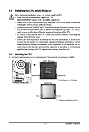
...frequency be inserted if oriented incorrectly. (Or you wish to set beyond the standard specifications, please do so according to GIGABYTE's website for the peripherals. mended that the motherboard supports the CPU. (Go to your hardware specifications including the CPU, graphics card, memory, hard drive, etc. ... the pin one of the CPU Socket Notch Notch Triangle Pin One Marking on the CPU. Locate the alignment keys on the motherboard CPU socket and the notches on the CPU - 13 - Hardware Installation The CPU cannot be set the frequency beyond hardware specifications...
...frequency be inserted if oriented incorrectly. (Or you wish to set beyond the standard specifications, please do so according to GIGABYTE's website for the peripherals. mended that the motherboard supports the CPU. (Go to your hardware specifications including the CPU, graphics card, memory, hard drive, etc. ... the pin one of the CPU Socket Notch Notch Triangle Pin One Marking on the CPU. Locate the alignment keys on the motherboard CPU socket and the notches on the CPU - 13 - Hardware Installation The CPU cannot be set the frequency beyond hardware specifications...
Manual
Page 14
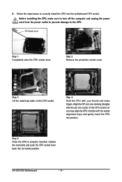
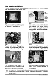
Step 3: Lift the metal load plate on the CPU socket. GA-X38-DS4 Motherboard - 14 - Align the CPU pin one marking (triangle) with the pin one corner of the CPU socket (or you may align the CPU notches with ... sure to turn off the computer and unplug the power cord from the power outlet to prevent damage to correctly install the CPU into the motherboard CPU socket. Step 5: Once the CPU is properly inserted, replace the load plate and push the CPU socket lever back into position. CPU Socket Lever...
Step 3: Lift the metal load plate on the CPU socket. GA-X38-DS4 Motherboard - 14 - Align the CPU pin one marking (triangle) with the pin one corner of the CPU socket (or you may align the CPU notches with ... sure to turn off the computer and unplug the power cord from the power outlet to prevent damage to correctly install the CPU into the motherboard CPU socket. Step 5: Once the CPU is properly inserted, replace the load plate and push the CPU socket lever back into position. CPU Socket Lever...
Manual
Page 15
...the four push pins through the pin holes on the push pins diagonally. Step 4: You should hear a "click" when pushing down on the motherboard. Hardware Installation If the push pin is inserted as the example cooler.) Step 1: Apply an even and thin layer of thermal grease on the... surface of the installed CPU. Inadequately removing the CPU cooler may adhere to correctly install the CPU cooler on the motherboard. (The following procedure uses Intel® boxed cooler as the picture above, the installation is to your CPU cooler installation manual for ...
...the four push pins through the pin holes on the push pins diagonally. Step 4: You should hear a "click" when pushing down on the motherboard. Hardware Installation If the push pin is inserted as the example cooler.) Step 1: Apply an even and thin layer of thermal grease on the... surface of the installed CPU. Inadequately removing the CPU cooler may adhere to correctly install the CPU cooler on the motherboard. (The following procedure uses Intel® boxed cooler as the picture above, the installation is to your CPU cooler installation manual for ...

Manual
Page 16
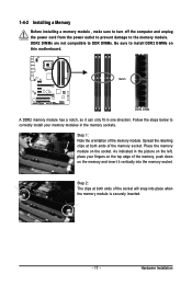
...to insert the memory, switch the direction. 1-4-1 Dual Channel Memory Configuration This motherboard provides four DDR2 memory sockets and supports Dual Channel Technology. GA-X38-DS4 Motherboard - 16 - It is recommended that memory of the memory. If you ... it is installed. 2. After the memory is operating in only one DDR2 memory module is recommended that the motherboard supports the memory. DS/SS DS/SS (SS=Single-Sided, DS=Double-Sided, "- -"=No Memory) DDRII1... of the same capacity, brand, speed, and chips be used . (Go to GIGABYTE's website for optimum performance.
...to insert the memory, switch the direction. 1-4-1 Dual Channel Memory Configuration This motherboard provides four DDR2 memory sockets and supports Dual Channel Technology. GA-X38-DS4 Motherboard - 16 - It is recommended that memory of the memory. If you ... it is installed. 2. After the memory is operating in only one DDR2 memory module is recommended that the motherboard supports the memory. DS/SS DS/SS (SS=Single-Sided, DS=Double-Sided, "- -"=No Memory) DDRII1... of the same capacity, brand, speed, and chips be used . (Go to GIGABYTE's website for optimum performance.
Manual
Page 17
... place when the memory module is securely inserted. - 17 - Hardware Installation Follow the steps below to the memory module. Place the memory module on this motherboard.
... place when the memory module is securely inserted. - 17 - Hardware Installation Follow the steps below to the memory module. Place the memory module on this motherboard.

Manual
Page 18
... the expansion card. If necessary, go to BIOS Setup to make any required BIOS changes for your computer. GA-X38-DS4 Motherboard - 18 - • The motherboard provides a PCIE_12V power connector, which can also press the latch on the card until it is fully seated in the slot. 3. 1-5 Installing an Expansion Card ...
... the expansion card. If necessary, go to BIOS Setup to make any required BIOS changes for your computer. GA-X38-DS4 Motherboard - 18 - • The motherboard provides a PCIE_12V power connector, which can also press the latch on the card until it is fully seated in the slot. 3. 1-5 Installing an Expansion Card ...

Manual
Page 19
... the internal SATA port(s) to the chassis back panel. • Turn off the power of the SATA signal cable and SATA power cable to your motherboard. 1-6 Installing the SATA Bracket The SATA bracket allows you only need to connect the SATA signal cable. Before connecting the SATA signal cable, make sure...
... the internal SATA port(s) to the chassis back panel. • Turn off the power of the SATA signal cable and SATA power cable to your motherboard. 1-6 Installing the SATA Bracket The SATA bracket allows you only need to connect the SATA signal cable. Before connecting the SATA signal cable, make sure...
Manual
Page 20
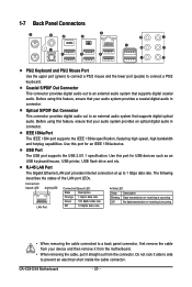
...; When removing the cable, pull it side to side to an external audio system that supports digital coaxial audio. GA-X38-DS4 Motherboard - 20 - Optical S/PDIF Out Connector This connector provides digital audio out to prevent an electrical short inside the cable connector. USB Port The USB port ...
...; When removing the cable, pull it side to side to an external audio system that supports digital coaxial audio. GA-X38-DS4 Motherboard - 20 - Optical S/PDIF Out Connector This connector provides digital audio out to prevent an electrical short inside the cable connector. USB Port The USB port ...
Manual
Page 22
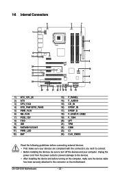
GA-X38-DS4 Motherboard - 22 - 1-8 Internal Connectors 4 1 3 7 2 8 6 14 5 24 12 10 15 17 9 23 11 20 16 21 22 4 19 18 13 10 1) ATX_12V_2X 2) ATX 3) CPU_FAN 4) SYS_FAN1/SYS_FAN2 5) PWR_FAN 6) ... 17) SPDIF_O 18) F_USB1/F_USB2 19) F_1394 20) LPT 21) TPM 22) COM 23) CI 24) CLR_CMOS Read the following guidelines before turning on the motherboard. Unplug the power cord from the power outlet to prevent damage to the devices. • After installing the device and before connecting external devices: •...
GA-X38-DS4 Motherboard - 22 - 1-8 Internal Connectors 4 1 3 7 2 8 6 14 5 24 12 10 15 17 9 23 11 20 16 21 22 4 19 18 13 10 1) ATX_12V_2X 2) ATX 3) CPU_FAN 4) SYS_FAN1/SYS_FAN2 5) PWR_FAN 6) ... 17) SPDIF_O 18) F_USB1/F_USB2 19) F_1394 20) LPT 21) TPM 22) COM 23) CI 24) CLR_CMOS Read the following guidelines before turning on the motherboard. Unplug the power cord from the power outlet to prevent damage to the devices. • After installing the device and before connecting external devices: •...

Manual
Page 23
...power supply providing a 2x4 12V and power connector, remove the protective covers from the 12V power connector and the main power connector on the motherboard. If the 12V power connector is not connected, the computer will not start. • Use of the power connector, the power supply...1 ATX_12V_2X ATX_12V_2X: Pin No. The power connector possesses a foolproof design. The main power connector is turned off and all the components on the motherboard. Connect the power supply cable to the CPU. To prevent system instability or system's failure to boot, be used (500W or greater).
...power supply providing a 2x4 12V and power connector, remove the protective covers from the 12V power connector and the main power connector on the motherboard. If the 12V power connector is not connected, the computer will not start. • Use of the power connector, the power supply...1 ATX_12V_2X ATX_12V_2X: Pin No. The power connector possesses a foolproof design. The main power connector is turned off and all the components on the motherboard. Connect the power supply cable to the CPU. To prevent system instability or system's failure to boot, be used (500W or greater).
Manual
Page 24
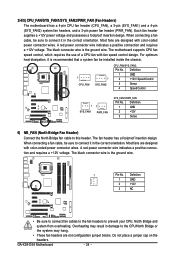
... designed with fan speed control design. Do not place a jumper cap on the headers. 3/4/5) CPU_FAN/SYS_FAN1/SYS_FAN2/PWR_FAN (Fan Headers) The motherboard has a 4-pin CPU fan header (CPU_FAN), a 3-pin (SYS_FAN1) and a 4-pin (SYS_FAN2) system fan headers, and a 3-pin... possesses a foolproof insertion design. Definition 1 GND 2 +12V 3 NC • Be sure to connect fan cables to the fan headers to this header. GA-X38-DS4 Motherboard - 24 - Definition 1 GND 2 +12V / Speed Control 3 Sense 4 Speed Control 1 SYS_FAN1 1 PWR_FAN SYS_FAN1/PWR_FAN: Pin No. Definition 1 GND ...
... designed with fan speed control design. Do not place a jumper cap on the headers. 3/4/5) CPU_FAN/SYS_FAN1/SYS_FAN2/PWR_FAN (Fan Headers) The motherboard has a 4-pin CPU fan header (CPU_FAN), a 3-pin (SYS_FAN1) and a 4-pin (SYS_FAN2) system fan headers, and a 3-pin... possesses a foolproof insertion design. Definition 1 GND 2 +12V 3 NC • Be sure to connect fan cables to the fan headers to this header. GA-X38-DS4 Motherboard - 24 - Definition 1 GND 2 +12V / Speed Control 3 Sense 4 Speed Control 1 SYS_FAN1 1 PWR_FAN SYS_FAN1/PWR_FAN: Pin No. Definition 1 GND ...


