
Manual
Page 1
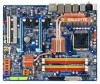
GA-X38-DQ6 LGA775 socket motherboard for Intel® CoreTM processor family/ Intel® Pentium® processor family/Intel® Celeron® processor family User's Manual Rev. 1002 12ME-X38DQ6-1002R
GA-X38-DQ6 LGA775 socket motherboard for Intel® CoreTM processor family/ Intel® Pentium® processor family/Intel® Celeron® processor family User's Manual Rev. 1002 12ME-X38DQ6-1002R

Manual
Page 2
Motherboard GA-X38-DQ6 Sept. 3, 2007 Motherboard GA-X38-DQ6 Sept. 3, 2007
Motherboard GA-X38-DQ6 Sept. 3, 2007 Motherboard GA-X38-DQ6 Sept. 3, 2007
Manual
Page 3
...product-related information, check on our website at: http://www.gigabyte.com.tw Identifying Your Motherboard Revision The revision number on our website. For example, "REV: 1.0" means the revision of the motherboard is the property of the product, read the Quick Installation Guide... by any form or by GIGABYTE without GIGABYTE's prior written permission. The trademarks mentioned in the use GIGABYTE's unique features, read or download the information on/from the Support\Motherboard\Technology Guide page on your motherboard revision before updating motherboard BIOS, drivers, or when ...
...product-related information, check on our website at: http://www.gigabyte.com.tw Identifying Your Motherboard Revision The revision number on our website. For example, "REV: 1.0" means the revision of the motherboard is the property of the product, read the Quick Installation Guide... by any form or by GIGABYTE without GIGABYTE's prior written permission. The trademarks mentioned in the use GIGABYTE's unique features, read or download the information on/from the Support\Motherboard\Technology Guide page on your motherboard revision before updating motherboard BIOS, drivers, or when ...

Manual
Page 4
Table of Contents Box Contents ...6 OptionalItems ...6 GA-X38-DQ6 Motherboard Layout 7 Block Diagram ...8 Chapter 1 Hardware Installation 9 1-1 Installation Precautions 9 1-2 Product Specifications 10 1-3 Installing the CPU and CPU Cooler 13 1-3-1 Installing the CPU 13 1-3-2 Installing the CPU Cooler 15 1-3-3 Removing the Crazy Cool Heatsink from the Back of the Motherboard ..... 16 1-4 Installing the Memory 17 1-4-1 Dual Channel Memory...
Table of Contents Box Contents ...6 OptionalItems ...6 GA-X38-DQ6 Motherboard Layout 7 Block Diagram ...8 Chapter 1 Hardware Installation 9 1-1 Installation Precautions 9 1-2 Product Specifications 10 1-3 Installing the CPU and CPU Cooler 13 1-3-1 Installing the CPU 13 1-3-2 Installing the CPU Cooler 15 1-3-3 Removing the Crazy Cool Heatsink from the Back of the Motherboard ..... 16 1-4 Installing the Memory 17 1-4-1 Dual Channel Memory...
Manual
Page 6
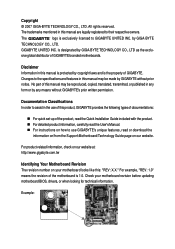
... in cable (Part No. 12CR1-1SPDIN-01R) COM port cable (Part No. 12CF1-1CM001-32R) LPT port cable (Part No. 12CF1-1LP001-01R) - 6 - Box Contents GA-X38-DQ6 motherboard Motherboard driver disk User's Manual Quick Installation Guide Intel® LGA775 CPU Installation Guide One IDE cable and one floppy disk drive cable Four SATA 3Gb...
... in cable (Part No. 12CR1-1SPDIN-01R) COM port cable (Part No. 12CF1-1CM001-32R) LPT port cable (Part No. 12CF1-1LP001-01R) - 6 - Box Contents GA-X38-DQ6 motherboard Motherboard driver disk User's Manual Quick Installation Guide Intel® LGA775 CPU Installation Guide One IDE cable and one floppy disk drive cable Four SATA 3Gb...

Manual
Page 7
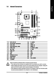
GA-X38-DQ6 Motherboard Layout KB_MS RCA_SPDIF USB_1394_1 SYS_FAN1 ATX_12V_2X LGA775 CPU_FAN PCIE_12V ATX USB_1394_2 USB_LAN USB_LAN2 PWR_FAN RTL8111B Intel® X38 AUDIO F_AUDIO PCIE_1 NB_FAN RTL8111B GA-X38-DQ6 FDD PCIE_16_1 DDRII1 DDRII2 DDRII3 DDRII4 CODEC CD_IN PCIE_2 PCIE_3 BP_BIOS MAIN_BIOS BAT PCIE_16_2 CLR_CMOS Intel® ICH9R SATAII0 IDE SATAII1 SPDIF_O PCI1 IT8718 PCI2 LPT CI COM TPM F_1394 F_USB2 F_USB1 TSB43AB23 GIGABYTE SATA2 SATAII4 SATAII2 GSATAIIA PWR_LED SPDIF_IN SYS_FAN2 F_PANEL SATAII5 SATAII3 GSATAIIB - 7 -
GA-X38-DQ6 Motherboard Layout KB_MS RCA_SPDIF USB_1394_1 SYS_FAN1 ATX_12V_2X LGA775 CPU_FAN PCIE_12V ATX USB_1394_2 USB_LAN USB_LAN2 PWR_FAN RTL8111B Intel® X38 AUDIO F_AUDIO PCIE_1 NB_FAN RTL8111B GA-X38-DQ6 FDD PCIE_16_1 DDRII1 DDRII2 DDRII3 DDRII4 CODEC CD_IN PCIE_2 PCIE_3 BP_BIOS MAIN_BIOS BAT PCIE_16_2 CLR_CMOS Intel® ICH9R SATAII0 IDE SATAII1 SPDIF_O PCI1 IT8718 PCI2 LPT CI COM TPM F_1394 F_USB2 F_USB1 TSB43AB23 GIGABYTE SATA2 SATAII4 SATAII2 GSATAIIA PWR_LED SPDIF_IN SYS_FAN2 F_PANEL SATAII5 SATAII3 GSATAIIB - 7 -
Manual
Page 9
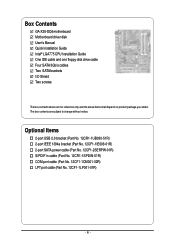
... have it on top of an antistatic pad or within an electrostatic shielding container. • Before unplugging the power supply cable from the motherboard, make sure the power supply has been turned off. • Before turning on the computer power during the installation process can become damaged...required for warranty validation. • Always remove the AC power by your hardware components are no leftover screws or metal components placed on the motherboard or within the computer casing. • Do not place the computer system on an uneven surface. • Do not place the computer ...
... have it on top of an antistatic pad or within an electrostatic shielding container. • Before unplugging the power supply cable from the motherboard, make sure the power supply has been turned off. • Before turning on the computer power during the installation process can become damaged...required for warranty validation. • Always remove the AC power by your hardware components are no leftover screws or metal components placed on the motherboard or within the computer casing. • Do not place the computer system on an uneven surface. • Do not place the computer ...
Manual
Page 10
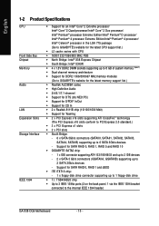
...GB of system memory (Note 1) Š Dual channel memory architecture Š Support for DDR2 1066/800/667 MHz memory modules (Go to GIGABYTE's website for the latest memory support list.) Š Realtek ALC889A codec Š High Definition Audio Š 2/4/5.1/7.1-channel Š Support for...SATA 3Gb/s devices - Support for SATA RAID 0, RAID 1, RAID 5 and RAID 10 Š GIGABYTE SATA2 chip: - 1 x IDE connector supporting ATA-133/100/66/33 and up to 2 IDE devices - 2 x SATA 3 Gb/s connectors (GSATAIIA, GSATAIIB) supporting up to the internal IEEE 1394 header) GA-X38-DQ6 Motherboard - 10 -
...GB of system memory (Note 1) Š Dual channel memory architecture Š Support for DDR2 1066/800/667 MHz memory modules (Go to GIGABYTE's website for the latest memory support list.) Š Realtek ALC889A codec Š High Definition Audio Š 2/4/5.1/7.1-channel Š Support for...SATA 3Gb/s devices - Support for SATA RAID 0, RAID 1, RAID 5 and RAID 10 Š GIGABYTE SATA2 chip: - 1 x IDE connector supporting ATA-133/100/66/33 and up to 2 IDE devices - 2 x SATA 3 Gb/s connectors (GSATAIIA, GSATAIIB) supporting up to the internal IEEE 1394 header) GA-X38-DQ6 Motherboard - 10 -
Manual
Page 12
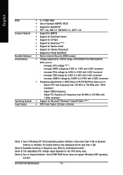
...in BIOS Setup (CPU/DDR2/PCIe) allow you to: - Adjust PCI Express x16 frequency from 100 MHz to 0.35V with 1 MHz increment - GA-X38-DQ6 Motherboard - 12 - English BIOS Unique Features Bundled Software Overclocking Operating System Form Factor Š 2 x 8 Mbit flash Š Use of physical memory... is installed, the actual memory size displayed will be less than 4 GB. (Note 2) Available functions in Easytune may differ by motherboard model. (Note 3) The adjustable CPU voltage range depends on the CPU being used. (Note 4) Due to : - Increase CPU voltage (Note ...
...in BIOS Setup (CPU/DDR2/PCIe) allow you to: - Adjust PCI Express x16 frequency from 100 MHz to 0.35V with 1 MHz increment - GA-X38-DQ6 Motherboard - 12 - English BIOS Unique Features Bundled Software Overclocking Operating System Form Factor Š 2 x 8 Mbit flash Š Use of physical memory... is installed, the actual memory size displayed will be less than 4 GB. (Note 2) Available functions in Easytune may differ by motherboard model. (Note 3) The adjustable CPU voltage range depends on the CPU being used. (Note 4) Due to : - Increase CPU voltage (Note ...
Manual
Page 13
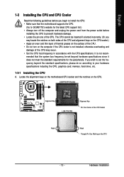
Locate the alignment keys on the motherboard CPU socket and the notches on the CPU - 13 - LGA775 CPU Socket Alignment Key LGA 775 CPU Alignment Key Pin One Corner of the CPU ....) • Apply an even and thin layer of thermal grease on the computer if the CPU cooler is not recom- mended that the motherboard supports the CPU. (Go to GIGABYTE's website for the peripherals. Hardware Installation English 1-3 Installing the CPU and CPU Cooler Read the following guidelines before installing the CPU to...
Locate the alignment keys on the motherboard CPU socket and the notches on the CPU - 13 - LGA775 CPU Socket Alignment Key LGA 775 CPU Alignment Key Pin One Corner of the CPU ....) • Apply an even and thin layer of thermal grease on the computer if the CPU cooler is not recom- mended that the motherboard supports the CPU. (Go to GIGABYTE's website for the peripherals. Hardware Installation English 1-3 Installing the CPU and CPU Cooler Read the following guidelines before installing the CPU to...
Manual
Page 14
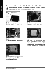
GA-X38-DQ6 Motherboard - 14 - Before installing the CPU, make sure to turn off the computer and unplug the power cord from the power outlet to prevent damage to correctly install the CPU into the motherboard CPU socket. Align the CPU pin one marking (triangle) with the pin one corner of the CPU socket (or you...
GA-X38-DQ6 Motherboard - 14 - Before installing the CPU, make sure to turn off the computer and unplug the power cord from the power outlet to prevent damage to correctly install the CPU into the motherboard CPU socket. Align the CPU pin one marking (triangle) with the pin one corner of the CPU socket (or you...

Manual
Page 15
...cooler, on the contrary, is to install.) Step 3: Place the cooler atop the CPU, aligning the four push pins through the pin holes on the motherboard. Hardware Installation Check that the Male and Female push pins are joined closely. (Refer to the CPU fan header (CPU_FAN) on the... 2: Before installing the cooler, note the direction of the arrow sign on the male push pin. (Turning the push pin along the direction of the motherboard. Step 4: You should hear a "click" when pushing down on the push pins diagonally. Use extreme care when removing the CPU cooler because the thermal ...
...cooler, on the contrary, is to install.) Step 3: Place the cooler atop the CPU, aligning the four push pins through the pin holes on the motherboard. Hardware Installation Check that the Male and Female push pins are joined closely. (Refer to the CPU fan header (CPU_FAN) on the... 2: Before installing the cooler, note the direction of the arrow sign on the male push pin. (Turning the push pin along the direction of the motherboard. Step 4: You should hear a "click" when pushing down on the push pins diagonally. Use extreme care when removing the CPU cooler because the thermal ...

Manual
Page 16
... on the North Bridge heatsink as shown in a safe place. Step 5: Do the same for damage of motherboard function(s) or component(s) resulting from the ones illustrated above. GA-X38-DQ6 Motherboard - 16 - Always keep the removed screws in the picture to the screw. On the front side of the...3: Step 4: After removing the spring nuts, remove the Crazy Cool heatsink from the back of the motherboard. 1. English 1-3-3 Removing the Crazy Cool Heatsink from the Back of the Motherboard To install a non-Intel CPU cooler that requires extra mounting holes, follow the steps below to remove ...
... on the North Bridge heatsink as shown in a safe place. Step 5: Do the same for damage of motherboard function(s) or component(s) resulting from the ones illustrated above. GA-X38-DQ6 Motherboard - 16 - Always keep the removed screws in the picture to the screw. On the front side of the...3: Step 4: After removing the spring nuts, remove the Crazy Cool heatsink from the back of the motherboard. 1. English 1-3-3 Removing the Crazy Cool Heatsink from the Back of the Motherboard To install a non-Intel CPU cooler that requires extra mounting holes, follow the steps below to remove ...

Manual
Page 17
... - DS/SS - - Intel® Flex Memory Technology offers greater flexibility to upgrade by allowing different memory sizes to be used . (Go to GIGABYTE's website for optimum performance. If you begin to install the memory: • Make sure that memory of the memory. Four Modules DS/SS DS/...four memory modules, it is recommended that memory of different capacity and chips are installed, a message which says memory is recommended that the motherboard supports the memory. When memory modules of the same capacity, brand, speed, and chips be populated and remain in only one DDR2 ...
... - DS/SS - - Intel® Flex Memory Technology offers greater flexibility to upgrade by allowing different memory sizes to be used . (Go to GIGABYTE's website for optimum performance. If you begin to install the memory: • Make sure that memory of the memory. Four Modules DS/SS DS/...four memory modules, it is recommended that memory of different capacity and chips are installed, a message which says memory is recommended that the motherboard supports the memory. When memory modules of the same capacity, brand, speed, and chips be populated and remain in only one DDR2 ...
Manual
Page 18
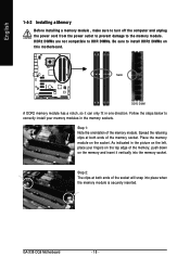
...the socket will snap into the memory socket. Step 2: The clips at both ends of the memory socket. Place the memory module on the socket. GA-X38-DQ6 Motherboard - 18 - As indicated in the picture on the left, place your memory modules in one direction. English 1-4-2 Installing a Memory Before installing a ...make sure to turn off the computer and unplug the power cord from the power outlet to prevent damage to install DDR2 DIMMs on this motherboard. Notch DDR2 DIMM A DDR2 memory module has a notch, so it vertically into place when the memory module is securely inserted. DDR2 ...
...the socket will snap into the memory socket. Step 2: The clips at both ends of the memory socket. Place the memory module on the socket. GA-X38-DQ6 Motherboard - 18 - As indicated in the picture on the left, place your memory modules in one direction. English 1-4-2 Installing a Memory Before installing a ...make sure to turn off the computer and unplug the power cord from the power outlet to prevent damage to install DDR2 DIMMs on this motherboard. Notch DDR2 DIMM A DDR2 memory module has a notch, so it vertically into place when the memory module is securely inserted. DDR2 ...
Manual
Page 19
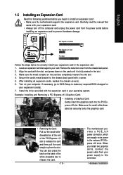
...the expansion slot. 1. Install the driver provided with a screw. 5. When you begin to install an expansion card: • Make sure the motherboard supports the expansion card. After installing all expansion cards, replace the chassis cover(s). 6. You can also press the latch on the card are ... Card: Pull out the small whitedrawable bar at the end of the white-drawable bar to release the card. - 19 - • The motherboard provides a PCIE_12V power connector, which can supply extra power to the onboard PCI Express x16 slots. English 1-5 Installing an Expansion Card Read the ...
...the expansion slot. 1. Install the driver provided with a screw. 5. When you begin to install an expansion card: • Make sure the motherboard supports the expansion card. After installing all expansion cards, replace the chassis cover(s). 6. You can also press the latch on the card are ... Card: Pull out the small whitedrawable bar at the end of the white-drawable bar to release the card. - 19 - • The motherboard provides a PCIE_12V power connector, which can supply extra power to the onboard PCI Express x16 slots. English 1-5 Installing an Expansion Card Read the ...
Manual
Page 20
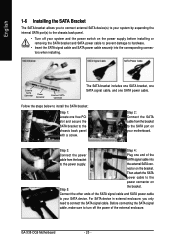
...from the bracket SATA signal cable into the corresponding connectors when installing. Then attach the SATA power cable to the power connector on your motherboard. Step 3: Step 4: Connect the power Plug one end of the cable from the bracket to the SATA port on Step 5: the...chassis back panel. • Turn off the power of the SATA signal cable and SATA power cable to connect the SATA signal cable. GA-X38-DQ6 Motherboard - 20 - SATA Bracket SATA Signal Cable SATA Power Cable External SATA Connector Power Connector External SATA Connector The SATA bracket includes one ...
...from the bracket SATA signal cable into the corresponding connectors when installing. Then attach the SATA power cable to the power connector on your motherboard. Step 3: Step 4: Connect the power Plug one end of the cable from the bracket to the SATA port on Step 5: the...chassis back panel. • Turn off the power of the SATA signal cable and SATA power cable to connect the SATA signal cable. GA-X38-DQ6 Motherboard - 20 - SATA Bracket SATA Signal Cable SATA Power Cable External SATA Connector Power Connector External SATA Connector The SATA bracket includes one ...
Manual
Page 21
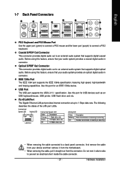
... LEDs. Optical S/PDIF Out Connector This connector provides digital audio out to an external audio system that your device and then remove it from the motherboard. • When removing the cable, pull it side to side to a back panel connector, first remove the cable from your audio system provides an optical...
... LEDs. Optical S/PDIF Out Connector This connector provides digital audio out to an external audio system that your device and then remove it from the motherboard. • When removing the cable, pull it side to side to a back panel connector, first remove the cable from your audio system provides an optical...
Manual
Page 22
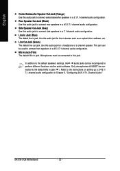
... center/subwoofer speakers in a 5.1/7.1-channel audio configuration. Mic In Jack (Pink) The default Mic in jack. Refer to perform different functions via the audio software. GA-X38-DQ6 Motherboard - 22 - This jack can be connected to connect front speakers in jack ( ). Line Out Jack (Green) The default line out jack. Microphones must be used...
... center/subwoofer speakers in a 5.1/7.1-channel audio configuration. Mic In Jack (Pink) The default Mic in jack. Refer to perform different functions via the audio software. GA-X38-DQ6 Motherboard - 22 - This jack can be connected to connect front speakers in jack ( ). Line Out Jack (Green) The default line out jack. Microphones must be used...
Manual
Page 23
..., make sure your devices are compliant with the connectors you wish to connect. • Before installing the devices, be sure to the connector on the motherboard. - 23 - Hardware Installation Unplug the power cord from the power outlet to prevent damage to the devices. • After installing the device and before connecting...
..., make sure your devices are compliant with the connectors you wish to connect. • Before installing the devices, be sure to the connector on the motherboard. - 23 - Hardware Installation Unplug the power cord from the power outlet to prevent damage to the devices. • After installing the device and before connecting...


